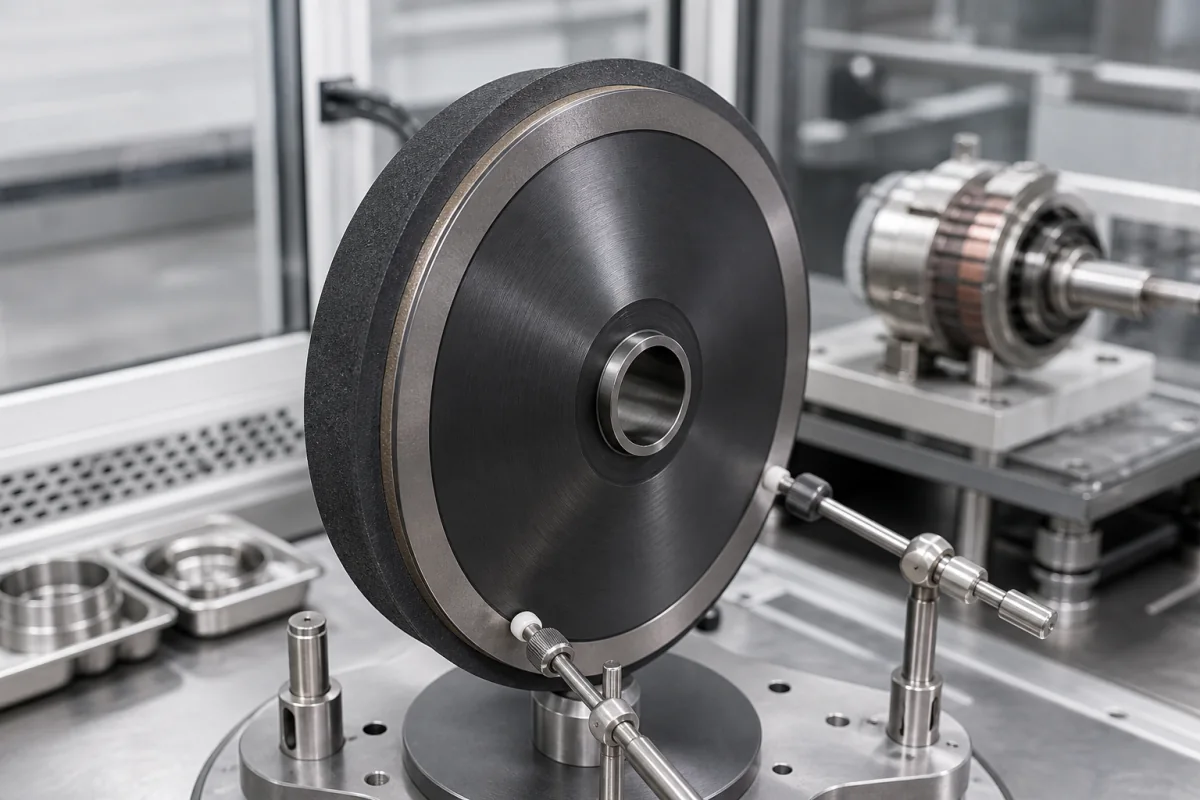
Rotating anode target discs for X-ray tubes · Tungsten-rhenium focal track on molybdenum with graphite backing, anode angle 6–22°, rotation 3,000–10,000 rpm, short- and long-exposure thermal limits, cracking and balance
A tungsten-rhenium target disc is the rotating anode of a diagnostic X-ray tube: a disc, for example molybdenum-bodied with graphite backing, carrying a tungsten-rhenium focal track that the electron beam strikes to produce X-rays, and spinning so the heat spreads around the track. Ask three things first: which tube power, exposure times and anode angle it must serve, how the focal track, body and backing are built to handle short-exposure stress and long-exposure heat, and what balance, bore and stem interface the rotor needs.
Rotating anode target discs for medical and industrial X-ray tubes, with tungsten or tungsten-rhenium focal tracks on molybdenum or composite bodies, with or without graphite backing. Complete X-ray tubes (see X-ray tube), stationary anodes, mammography molybdenum or rhodium targets and sputtering targets are outside this page.
CNFX editorial research · Sources checked October 12, 2026 · 5 sources
Match the disc to the tube load and exposure pattern
The IAEA handbook Diagnostic Radiology Physics (2014) says X-ray production at 100 kV converts only about 0.8% of electrical power to radiation, so nearly all tube power becomes heat in the anode. A rotating anode spreads the bombarded area over the circumference of a focal track, with the disc fixed to a rotor and spindle on ball or liquid-metal bearings. [1]
Within the first 100 ms of an exposure the maximum load is set by mechanical stress from temperature gradients near the focal spot, which can crack the surface; the handbook says this can be reduced with a more ductile focal-track alloy such as tungsten-rhenium, a larger focal spot or faster rotation. For exposures up to a few seconds the limit is the focal-spot temperature, up to 2,757 °C for tungsten; for CT and fluoroscopy exposures of 10 s to over 200 s the heat capacity and conduction of the whole disc matter, where molybdenum is superior to tungsten and graphite backing adds heat capacity and radiates heat, while larger discs become harder to balance across the temperature range. [1]
Editorial calculation: a 50 kW tube exposure converts about 0.8% to X-rays, so about 49.6 kW reaches the anode as heat; over a 0.1 s exposure that is about 5 kJ into the focal track. Ask the tube maker for the anode heat capacity and cooling curve that the disc must meet. [1]
Give the supplier the tube type and power, exposure pattern (radiography, fluoroscopy, CT), anode angle, disc diameter and thickness, focal-track material and rhenium content, body material, graphite backing, target heat capacity, bore and stem interface, balance grade, rotation speed, vacuum processing and outgassing requirements, inspection (ultrasonic, X-ray) and quantities.
02
Fix the anode angle, rotation speed and layer build
The handbook explains the line-focus principle: the anode is inclined so the electronic focus appears shortened by sin θ in the beam direction. Anode angles in diagnostic tubes range from 6° to 22°, with 10–16° for general-purpose tubes, limited by field coverage and the heel effect. [1]
The rotor is an induction motor with a copper squirrel-cage; speed is set by supply frequency and active stator windings, switching between about 9,000–10,000 rpm and 3,000–3,600 rpm, with low speed used for low-current fluoroscopy. It notes that bearings and the whole assembly undergo large thermal cycling and high thermal stresses. [1]
Editorial calculation: at a 12° anode angle an electron focus 5 mm long appears as about 5 × sin 12° ≈ 1.0 mm in the beam direction; a smaller angle gives a smaller effective spot for the same track loading but cuts field coverage. [1]
03
Check the tube-level rules the disc must support
In the United States, 21 CFR 892.1760 classifies the diagnostic x-ray tube housing assembly — the x-ray tube in a radiation-shielded housing, possibly with high-voltage and filament transformers — as a Class I device under general controls, exempt from premarket notification within the limits of § 892.9. The target disc is a component of that tube, so the tube maker carries the device obligations. [2]
The US performance standard at 21 CFR 1020.30 limits leakage radiation from the diagnostic source assembly to 0.88 mGy air kerma (formerly stated as 100 mR) in one hour at 1 m in any direction when the tube runs at its leakage technique factors, averaged over an area of 100 cm². Shielding is a housing design matter, but the disc's rated power and the tube's rated peak potential set the leakage technique factors that the test uses. [3]
Editorial calculation: 0.88 mGy per hour is about 0.88 ÷ 60 ≈ 0.015 mGy per minute of continuous operation at the leakage technique factors, so ask the tube maker for the leakage test report alongside the disc's heat-storage and power ratings. [3]
04
Tie the disc to the IEC tests the tube assembly will face
Two IEC standards describe how the tube a target disc goes into is characterised. IEC 60613:2010 "applies to X-ray tube assemblies either with a rotating anode X-ray tube or a stationary anode X-ray tube, intended for use in medical diagnosis" and covers performance-related definitions and conditions of electrical and loading characteristics during and after energization, with methods of presentation and measurement; its third edition replaced the 1989 second edition. IEC 60336:2020 applies to focal spots in medical diagnostic X-ray tube assemblies operating at tube voltages up to and including 150 kV, with test methods using digital detectors for nominal focal spot values from 0,1 to 3,0. [4][5]
The IAEA handbook explains that the focal track, anode angle and rotation speed determine how heat from the focal spot is spread and how the line-focus principle shortens the apparent spot [1]. Where the tube maker rates the finished assembly to IEC 60613 and states its focal spots per IEC 60336 [4][5], ask the disc supplier for the track radius, track width and angle tolerance that the tube maker's focal spot and loading data depend on.
In the United States the finished housing assembly falls under 21 CFR 892.1760 [2], and leakage radiation limits apply under 21 CFR 1020.30 [3]. These rules apply to the tube maker; ask the disc supplier which drawing, material certificate and balance records it supplies with each disc lot.
Editorial calculation: IEC 60336's nominal focal spot range spans a factor of 30 (0,1 to 3,0); IEC 60613's 2010 edition replaced one published 21 years earlier, and IEC 60336:2020 one 15 years earlier. [5][4]
Item
IEC 60613:2010
IEC 60336:2020
Subject
Electrical and loading characteristics of X-ray tube assemblies
Focal spot characteristics
Scope limits
Rotating or stationary anode tubes for medical diagnosis
Tube voltages up to and including 150 kV; nominal focal spot values 0,1 to 3,0
Measured
Behaviour during and after energization
Focal spot dimensions, line spread functions, one-dimensional MTF, pinhole radiograms
Edition and date
Edition 3, 27 January 2010
Edition 5, 17 December 2020
Replaced
Edition 2 (1989)
Edition 4 (2005); now digital detectors, fewer normative requirements
Values are from the Standard Norge catalogue pages for IEC 60613:2010 and IEC 60336:2020; the full standards were not reviewed.
05
Drawing data and lot records to exchange with a disc maker
A disc is made to the tube maker's drawing: send the anode angle, track radius and width, rhenium content, body alloy, graphite backing, bore and stem interface and balance grade, and ask which drawing, material certificate, balance and inspection records come with each disc lot.
The layers answer different exposures: the tungsten-rhenium track the surface stress of the first 100 ms, the molybdenum body and graphite backing the heat of CT and fluoroscopy runs from 10 s to over 200 s. [1]
Anode angle, rotation speed, track alloy, temperature limit and heat capacity for a disc order
Inspection is the one row with no published basis in the sources, so the bond and crack checks and their acceptance limits have to be agreed with the supplier.
Explore company information and manufacturing capabilities, then discuss the scope of your project with a relevant supplier.
Share this page
Compiled and source-reviewed by the CNFX editorial team.
Each manufacturer above links to the page on that company's own website where the product is listed, with the date we checked it. How we source and review
· Page last updated 13 October 2026
Buyer questions
Why use tungsten-rhenium for the focal track?
The IAEA handbook says a more ductile tungsten-rhenium alloy reduces surface cracking from thermal stress in the first 100 ms of an exposure. [1]
How fast do rotating anodes turn?
About 9,000–10,000 rpm at high speed and 3,000–3,600 rpm at low speed. [1]
Why add graphite to the back of the disc?
Graphite raises heat capacity at high temperature and dissipates heat by thermal radiation, which matters for long CT and fluoroscopy exposures. [1]
What leakage radiation limit applies to the x-ray tube a target disc goes into?
21 CFR 1020.30 limits leakage from the diagnostic source assembly to 0.88 mGy air kerma in one hour at 1 m at the leakage technique factors. [3]
Which IEC standards cover rotating anode X-ray tube performance?
IEC 60613:2010 covers electrical and loading characteristics of X-ray tube assemblies for medical diagnosis, and IEC 60336:2020 covers focal spot measurement for tubes up to 150 kV with nominal focal spot values from 0.1 to 3.0. [4][5]
Sources and what still needs a direct check
Sources checked 2026-10-12. The IAEA handbook (2014) is a teaching text on diagnostic radiology physics; it is not a component specification. Values for your disc must come from the tube maker's drawing and the supplier's tests.