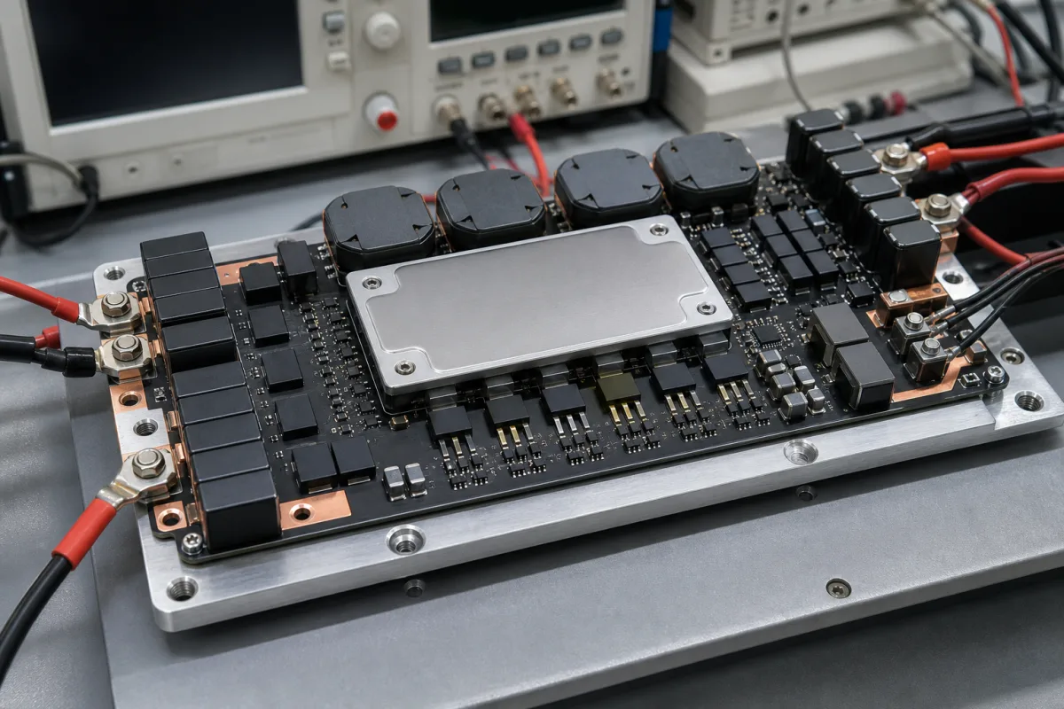
Multiphase voltage regulator modules for processors, ASICs and FPGAs · Input range and output-voltage programming, phase count and power stages, transient response, phase shedding, telemetry and thermal design
A voltage regulator module (VRM) is the multiphase step-down converter beside a processor, ASIC, FPGA or GPU that turns a 12 V-class bus into a low, tightly regulated core voltage at hundreds of amps, changing voltage on command. Settle three things before ordering: the input range, output-voltage range and step, and peak and continuous current; the phase count, power stages and transient response; and the efficiency features, telemetry, layout and cooling.
Multiphase VRM controllers, smart power stages and complete VRM/point-of-load modules for processor, ASIC, FPGA and GPU core rails. Single-phase buck converters, LDOs, isolated DC-DC bricks and AC-DC supplies are outside this page; DC-DC converters and LDOs have their own pages.
CNFX editorial research · Sources checked October 11, 2026 · 4 sources
TI's TPS53681 datasheet describes a dual-channel multiphase step-down controller with non-volatile memory and a PMBus interface. It lists a conversion input range of 4.5 V to 17 V, an 8-bit DAC with selectable 5 mV or 10 mV resolution and output ranges of 0.25–1.52 V or 0.5–2.8125 V for the two channels, and phase configurations up to six phases plus two or five plus three, down to one plus one. Applications include networking processors, data-centre and campus switches, routers and high-current FPGA power. [1]
The controller pairs with TI smart power stages; TI's CSD95490Q5MC lists 75 A continuous operating current, over 95% system efficiency at 30 A, operation up to 1.25 MHz, temperature-compensated bidirectional current sense, analog temperature output, fault monitoring and a 5 × 6 mm QFN with top-side cooling, for multiphase synchronous buck converters. [2]
Editorial calculation: six phases of a 75 A power stage give a theoretical 450 A of stage capability on one rail; the usable continuous current is lower and depends on switching frequency, inductors, airflow and board copper, so ask for the thermal derating at your conditions. [1][2]
Give the supplier the input bus range, output voltage range and step (VID or PMBus), continuous and peak current, load-step size and slew, allowed undershoot and overshoot, ripple, number of rails, phase count preference, switching frequency, efficiency target at light and full load, telemetry and fault reporting needs, layout area and height, airflow and temperature, and quantity.
02
Check phase management, transient response and telemetry
The TPS53681 uses a D-CAP+ architecture with undershoot reduction (USR) for fast transient response and low output capacitance, fast phase adding, dynamic phase shedding with a programmable current threshold for efficiency across load, patented AutoBalance phase balancing, a selectable 16-level per-phase current limit, individual phase current calibration and reporting, adjustable voltage positioning, and dynamic output-voltage transitions with programmable slew rates. [1]
Its PMBus interface reports voltage, current, power, temperature and fault conditions, and all programmable parameters can be stored in NVM as defaults to reduce external components. It switches at 300 kHz to 1 MHz with closed-loop frequency control, comes in a 5 × 5 mm 40-pin QFN PowerPad package and is rated from −40 to +125 °C. [1]
Editorial note: ask for the load-step test with your capacitor bank — undershoot, overshoot and settling — and for efficiency curves with and without phase shedding at your load profile. [1]
03
Phase count, current rating, transient and thermal data to request with a VRM quote
Ask any supplier for the reference design or module data with phase count, current rating, transient results and thermal data. [1][2]
04
Write the load line, load step and phase current into your RFQ
TI's application report SLVA882B works through a multiphase design for the core rail of a networking ASIC, with targets of 12 V input, 0.9 V output, 200 A thermal design current, 240 A maximum, a 150 A load step, a 0.5 mΩ DC load line, ±1% DC ripple and ±5% transient tolerance. TI gives a guideline of keeping maximum phase current between 30 and 40 A; the example therefore uses six phases, carrying 33 A per phase at the thermal design current and 40 A at maximum. [3] With the load line, TI explains, the 0.9 V rail drops by 100 mV to 0.8 V at 200 A, which lowers processor power by 20 W and reduces the output capacitance needed for transients. [3]
TI's sizing shows that the load release, not the load step, sets the output capacitor bank: in the example the undershoot needs 211.1 µF while the overshoot on release needs 2,604 µF, and TI sets each capacitor mix it compares higher than the overshoot value to provide margin and account for MLCC derating. [3] TI chose 600 kHz switching as a trade-off, noting that frequencies around 300 kHz give lower switching loss but slower transient response and that frequencies around 1 MHz respond faster with greater switching loss. [3] Editorial note: state the load line, load-step size and the release case in the RFQ, and ask the supplier which capacitor bank its transient result was measured with.
05
Name the processor VR specification and the power-stage pairing
For an Intel server, workstation or high-end desktop core rail, write the processor's VR specification revision into the order. Infineon's XDPE15284D datasheet states compliance with the Intel VR13, VR13HC and VR14 Server VR Vendor PWM Enabling Specification Rev 1.88 (October 2021), the Intel SVID Protocol Spec Rev 1.94 (April 2021) and PMBus Rev 1.3.1, with a maximum bus speed of 1 MHz at 1.8 V or 3.3 V. The controller runs up to 8 phases over two loops, with any phase assignable to either loop, and gives output ranges of 0.25 V to 1.52 V in 5 mV steps or 0.5 V to 3.04 V in 10 mV steps, offset and trim resolution of 625 uV and accuracy better than 0.5%. [4]
Infineon lists digital current emulation for trans-inductor voltage regulator (TLVR) inductors, TLVR secondary open/short detection, peak phase current pulse limiting and negative current limit protection, alongside input and output under- and over-voltage, total-current and over-temperature protection. It also states that interoperability with other vendors' power stages or discrete parts cannot be guaranteed by Infineon and requires evaluation by that vendor, so ask which power stage the quoted controller was characterised with. [4]
Configurations live in internal NVM; Infineon notes that factory pre-programmed customer configurations carry significantly longer sample lead times than the default configuration. Its qualification table gives industrial level, MSL1 for the QFN package, HBM ESD to JESD22-A114-F Class 2, CDM to JESD22-C101-F Class C3 and latch-up to JESD78D Class 2. Editorial note: state in the RFQ whether you need a customer configuration ID and request the qualification report. [4]
06
Controller, DAC, smart power stages, inductors, PMBus and thermal path
The work splits between two TI parts: the TPS53681 controller sets phase count, output-voltage steps and PMBus telemetry, while each CSD95490Q5MC stage carries one phase's current and reports its current and temperature. [1][2]
Input range, VID step, per-stage current, efficiency and package size for a VRM order
Published values here come from the TPS53681 controller and the CSD95490Q5MC power stage; line regulation, storage temperature, humidity, IP rating and weight have no published value and must come from the module supplier.
3 companies list this product among what they make. Company figures are quoted from each
company's own website; every card states where the relationship came from.
Explore company information and manufacturing capabilities, then discuss the scope of your project with a relevant supplier.
Share this page
Compiled and source-reviewed by the CNFX editorial team.
Each manufacturer above links to the page on that company's own website where the product is listed, with the date we checked it. How we source and review
· Page last updated 13 October 2026
Buyer questions
How many phases can a VRM controller run?
TI's TPS53681 supports up to six plus two (or five plus three) phases on two channels. [1]
How is VRM output voltage set?
The TPS53681 uses an 8-bit DAC with 5 or 10 mV steps, programmable over PMBus. [1]
How much current does each phase carry?
TI's CSD95490Q5MC power stage is rated 75 A continuous. [2]
What is phase shedding?
Dropping phases at light load to improve efficiency; the TPS53681 does this with a programmable current threshold. [1]
What current per phase should a multiphase VRM be designed for?
Texas Instruments' application report SLVA882B gives a guideline of keeping maximum phase current between 30 and 40 A; its 240 A example uses six phases, 40 A each at maximum. [3]
Which Intel VR specification should a VRM controller comply with?
Ask for the revision your processor needs; Infineon's XDPE15284D datasheet, for example, states compliance with the Intel VR13, VR13HC and VR14 Server VR Vendor PWM Enabling Specification Rev 1.88 and SVID Protocol Spec Rev 1.94. [4]
Sources and what still needs a direct check
Sources checked 2026-10-11. Texas Instruments publishes the TPS53681 controller and CSD95490Q5MC power-stage datasheets and the SLVA882B multiphase design report; Infineon publishes the XDPE15284D controller datasheet.