Editorial Technical Reference

Core Clamping System

This page explains how Core Clamping System is classified within Electrical Equipment Manufacturing. Technical values and manufacturer relationships are research references; confirm the current specification and supplier evidence for each order.

Technical Definition & Core Assembly

A mechanical assembly that securely clamps and holds the magnetic core in place within a medium voltage current transformer.
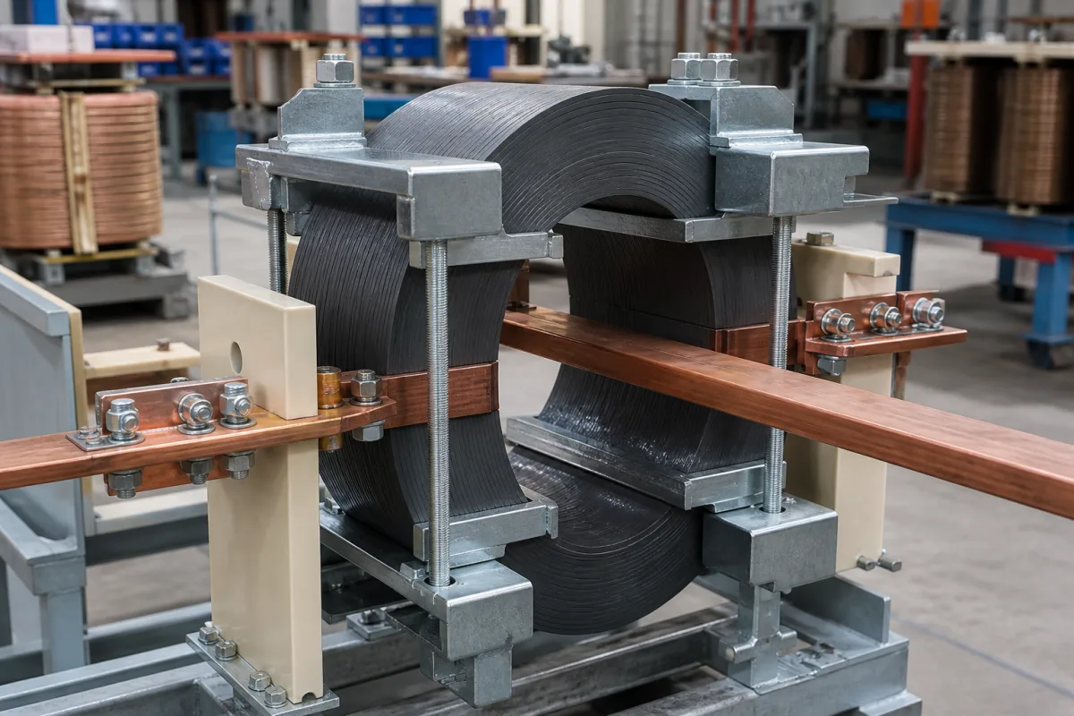
Representative product image. Confirm appearance and specifications with the manufacturer.

Product Specifications

Technical details and manufacturing context for Core Clamping System

Definition
The Core Clamping System is a critical component of the Medium Voltage Current Transformer Core Assembly, designed to apply precise and uniform pressure to the laminated magnetic core stack. It ensures the core remains stable, prevents vibration-induced noise, maintains proper magnetic circuit integrity, and protects against mechanical stress during operation and transportation. The system typically uses a combination of clamping plates, bolts, springs, and insulating components to apply controlled compressive force to the core laminations. This force minimizes air gaps between laminations, reduces magnetic losses (eddy currents and hysteresis), and ensures the core maintains its structural and electrical integrity under varying thermal and electromagnetic conditions. The system is available in configurations suitable for core diameters from 50 to 300 mm and core heights from 30 to 200 mm, with a clamping force range of 5 to 20 kN. Clamping pressure is specified between 1.0 and 1.6 MPa. Surface flatness of clamping plates is maintained within 0.05 mm per ISO 1101 to ensure uniform pressure distribution. Insulation resistance between clamping parts and the core is at least 1000 MΩ at 500 V DC, and dielectric strength is at least 5 kV, both per IEC 60243. The system operates within a temperature range of -40°C to 85°C (IEC 60068-2-1) and withstands relative humidity up to 95% non-condensing at 40°C (IEC 60068-2-78). Ingress protection ratings range from IP54 to IP65 per IEC 60529. Structural parts are made of Q235B carbon steel (GB/T 700) with hot-dip galvanized surface treatment (Zn-8–12 μm) per ISO 1461. Weight varies from 2 to 15 kg depending on core size and configuration. All listed values are reference ranges; verify model-specific parameters and standards with the legal manufacturer or supplier before procurement.
Working Principle
The system applies controlled compressive force to the laminated core stack using clamping plates, bolts, springs, and insulating components. This force minimizes air gaps between laminations, reducing magnetic losses such as eddy currents and hysteresis. It also maintains structural integrity under thermal expansion and electromagnetic forces, preventing vibration-induced noise and ensuring stable magnetic circuit performance. The clamping pressure is set within a range that avoids damaging the core.
Common Materials
Cold-rolled steel, Stainless steel, Insulating epoxy laminate
Technical Parameters
ParameterTypical rangeNotes & selection driver
Clamping Force5–20 kNEnsures core stability under short-circuit conditions
Core Diameter Range50–300 mmAccommodates standard medium voltage transformer cores
Core Height Range30–200 mmFits typical core stack heights
Surface Flatness≤0.05 mmEnsures uniform pressure distributionISO 1101
Insulation Resistance≥1000 At 500 V DC, between clamping parts and coreIEC 60243
Dielectric Strength≥5 kVWithstands test voltage without breakdownIEC 60243
Operating Temperature-40–85 °CContinuous operation within this rangeIEC 60068-2-1
Relative Humidity≤95 %Non-condensing at 40°CIEC 60068-2-78
Ingress ProtectionIP54–IP65Protection against dust and water jetsIEC 60529
Material GradeQ235BCarbon steel for structural partsGB/T 700
Surface TreatmentZn-8–12 μmHot-dip galvanized for corrosion resistanceISO 1461
Weight2–15 kgDepends on core size and configuration

Ranges are indicative industry figures for RFQ preparation, not a supplier commitment. Confirm every value and standard with the legal manufacturer before ordering.

Components / BOM
  • Clamping Plate Part
    Distributes clamping force evenly across core surface
    Material: Cold-rolled steel
  • Insulating Spacer Part
    Provides electrical isolation between core and clamping structure
    Material: Epoxy laminate
  • Tensioning Bolt Part
    Applies and maintains precise clamping pressure
    Material: Stainless steel
  • Clamping Springs
    Keep the clamping force constant as the core stack settles and expands with temperature.

Industrial Ecosystem & Supply Chain Structure

Complementary Systems
Downstream Applications
Specialized Tooling

Application Fit & Sizing Matrix

Operational Limits
pressure: Max clamping force: 5000 N, Max compressive stress: 50 MPa
other spec: Core diameter range: 50-300 mm, Vibration resistance: 5g @ 10-2000 Hz, Insulation class: F (155°C)
temperature: -40°C to +85°C
Media Compatibility
✓ Silicon steel laminated cores ✓ Nanocrystalline magnetic cores ✓ Ferrite magnetic cores
Unsuitable: Corrosive chemical environments (acids, alkalis, salt spray)
Sizing Data Required
  • Core outer diameter and length
  • Required clamping force for magnetic performance
  • Transformer housing dimensions and mounting constraints

Reliability & Engineering Risk Analysis

Failure Mode & Root Cause
Hydraulic Seal Degradation
Cause: Contamination of hydraulic fluid with particulate matter leading to abrasive wear, or chemical incompatibility causing seal swelling/brittleness.
Mechanical Fatigue/Cracking of Clamping Components
Cause: Cyclic overloading beyond design limits due to improper pressure settings or shock loads from the process, leading to stress concentration and eventual fracture.
Maintenance Indicators
  • Visible hydraulic fluid leaks around cylinder seals or fittings, indicating seal failure.
  • Abnormal audible noises during clamping (e.g., knocking, grinding, or hissing), suggesting mechanical wear or hydraulic issues.
Engineering Tips
  • Implement a strict hydraulic fluid cleanliness program with regular filtration and analysis to prevent contamination-induced failures.
  • Conduct periodic torque or pressure calibration checks to ensure clamping forces remain within specified design limits, preventing overstress.

Indicative industry ranges for design and RFQ preparation. Confirm the exact figures and applicable standard with the manufacturer before specifying.

Compliance & Manufacturing Standards

Applicable Standards
ANSI B11.19 - Performance Requirements for Safeguarding DIN 5480 - Involute Splines Based on Reference Diameters

Quoted from the published standard.

Manufacturing Precision
  • Bore Diameter: +/-0.01mm
  • Parallelism of Clamping Faces: 0.05mm
Quality Inspection
  • Dimensional Verification with CMM
  • Hardness Testing (Rockwell C Scale)

Manufacturers of Core Clamping System

Manufacturer profiles associated with Core Clamping System.

Sourcing Core Clamping System from China?
Tell us your specification and target quantity — we will match it against manufacturer records and come back with the factories that fit.
Request manufacturers We manufacture this

Manufacturer listings support early research and capability understanding. They are not certification, ranking, or transaction guarantees.

Technical documentation
Request current drawings, revision history, and a signed specification sheet.
Manufacturing capability
Verify equipment lists, process limits, capacity, and representative production evidence.
Inspection readiness
Confirm test methods, calibrated equipment, sampling plans, and traceable reports.
Supplier transparency
Check the legal entity, factory address, ownership, certifications, and direct contacts.

CNFX does not score or rank suppliers. Buyers must verify all claims and documents with the legal manufacturer before ordering.

Supply Chain Compatible Machinery & Devices

Motor Terminal Block

A motor terminal block is a standardized electrical component that provides secure, insulated connection points for motor winding leads.

Explore Specs →
PLC Control System

A digital industrial computer control system that monitors inputs, makes decisions based on a custom program, and controls outputs to automate industrial processes.

Explore Specs →
Control Panel

A centralized interface for monitoring and controlling industrial equipment and processes

Explore Specs →
PLC Control Panel

A centralized interface unit housing the programmable logic controller and associated control components for industrial automation systems.

Explore Specs →

Frequently Asked Questions

What is the function of the Core Clamping System?

It securely clamps the laminated magnetic core in a medium voltage current transformer, applying uniform pressure to minimize air gaps, reduce magnetic losses, and prevent vibration-induced noise, ensuring stable operation.

What are the typical clamping force and pressure ranges?

The clamping force is typically 5–20 kN, and the clamping pressure is 1.0–1.6 MPa. These are reference ranges; confirm exact values for your model.

What standards apply to the insulation properties?

Insulation resistance is ≥1000 MΩ at 500 V DC, and dielectric strength is ≥5 kV, both per IEC 60243. These ensure electrical safety between clamping parts and the core.

How does the system handle environmental conditions?

It operates from -40°C to 85°C (IEC 60068-2-1) and up to 95% relative humidity non-condensing at 40°C (IEC 60068-2-78). Ingress protection is IP54–IP65 per IEC 60529, protecting against dust and water jets.

Data Basis

Editorial classification, named public sources where available, and source-reviewed manufacturer records.

Preliminary Technical Classification
This page supports structured research, RFQ preparation, and supplier evaluation. It does not replace buyer-led supplier qualification, standards review, or technical approval.
Buyer enquiry

Request manufacturing insight for Core Clamping System

Ask for use case, specification boundaries, supplier type, and RFQ preparation information for this product.

Where it goes
Straight to the CNFX editorial desk, and to the manufacturer if this product is linked to a claimed profile. Nothing is broadcast to a supplier list.
Your details stay here
We do not sell or rent enquiry data, and we do not add you to a mailing list. Used only to answer this request.
No commission, no middleman
CNFX is a directory. We take no cut of any order and never negotiate on a supplier's behalf.
What we don't claim
A listing is not an endorsement. Qualify every supplier and verify every figure yourself before ordering.

Your business information is used only to process this request.

Thank you! Your message has been sent. We'll respond within 1–3 business days.
Sorry, we couldn't send your message. Please try again, or email us at contact@cnfx.com.

Need to Manufacture Core Clamping System?

Compare manufacturer profiles with relevant product and process capability.

Previous Product
Wire Tensioning System
Last Product
Get QuotesChat