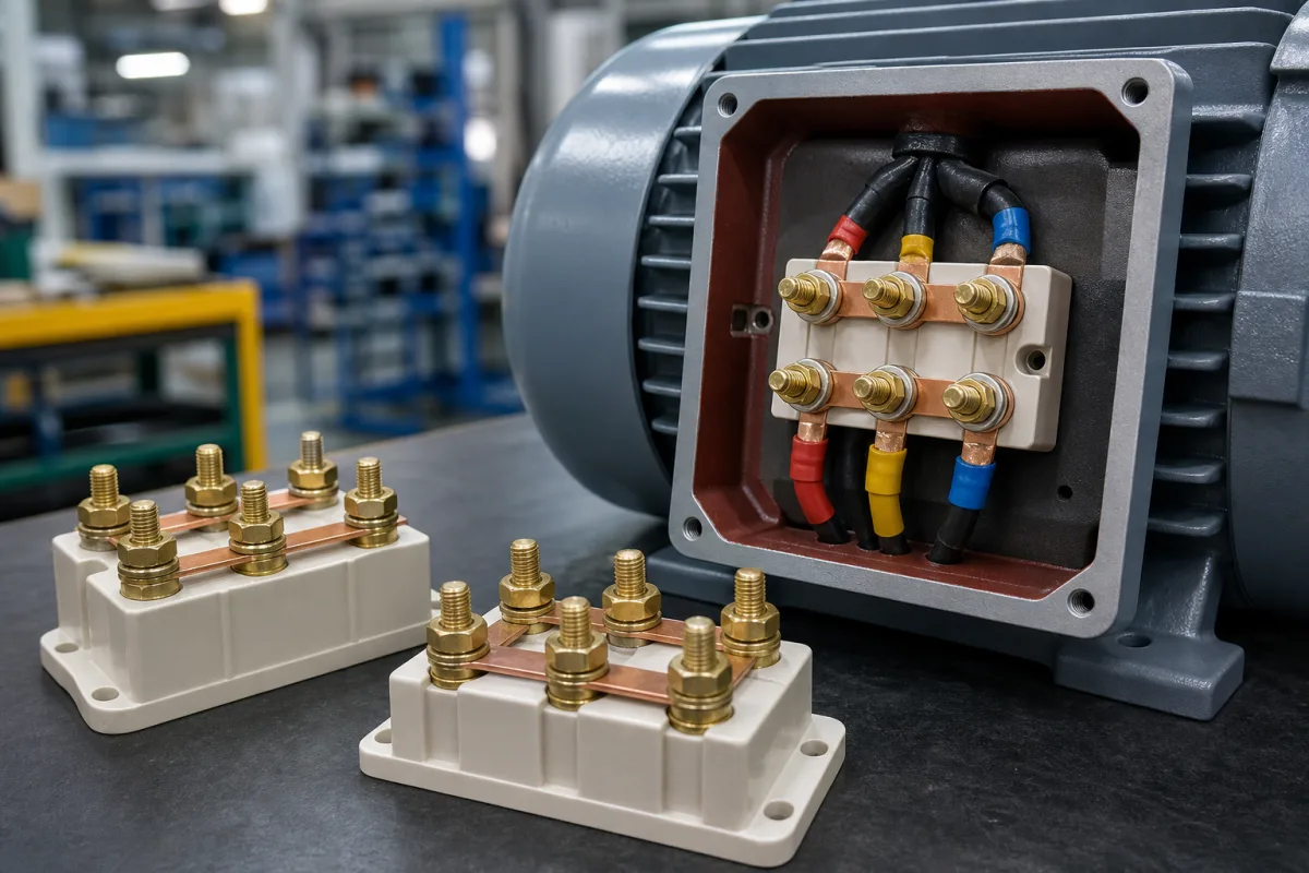
Motor terminal board: the six-stud ceramic block in the motor terminal box, with star and delta links
The six-stud board inside a motor's terminal box · stud size against current and tightening torque, star and delta links on the same studs, and the board without links when a star-delta starter takes six leads
A three-phase motor brings both ends of each winding into its terminal box — U1, V1, W1 and U2, V2, W2 — and lands them on a board with six threaded studs in two rows of three. Short copper links laid across the studs connect the windings in star or in delta, and the supply cable lugs go on the same studs under the nuts. The board is a small part with three jobs at once: it carries the full motor current through brass studs, it insulates the phases from each other and from the earthed box, and it lets the connection be changed in the field. What distinguishes one board from another is the stud thread, the current each stud can carry, the torque the studs and the mounting screws take, and the insulation material.
Six-stud motor terminal boards (terminal plates) for three-phase motor terminal boxes, similar to DIN 46294, with brass studs, nuts and washers, star/delta links and ceramic or moulded insulating bases. DIN-rail, PCB, pluggable and barrier terminal blocks for control panels are covered on the Terminal block page, and rail-mounted feed-through blocks for 50–240 mm² power cables on the High-current power terminal block for large cables page; this board is mounted inside the motor and takes cable lugs on threaded studs. Complete terminal boxes, cable glands and motor starters are outside this page.
CNFX editorial research · Sources checked October 12, 2026 · 3 sources
Stud thread against current and torque: M4 at 16 A and 1.2 Nm up to M10 at 160 A and 10 Nm
WECO's 711–717 series are six-pole motor terminal boards similar to DIN 46294, designated K1 M4 to K1 M10 after that standard. The stud thread sets the allowed continuous current through the bushing bolt and the nut torque; the board's own fixing screw has a separate, much lower limit. [1]
The boards are rated up to 660 V, with higher voltages possible depending on size and installation as long as clearances and creepage distances are observed; the rated voltage applies only when the board is mounted on an insulating substrate, and every variant is to be installed with a matching washer on an elastic, insulating base. [1] The base is technical ceramic with a comparative tracking index of at least 600, insulating group I and a range of −40 °C to 250 °C; studs and nuts are bare brass and washers zinc-plated steel, and the rated cross-section depends on the cable lugs used. [1]
Editorial calculation: the current step from M5 (25 A) to M6 (63 A) is 2.5 times, while the stud torque rises only from 2.0 to 3.0 Nm, so the current rating, not the thread alone, should drive the choice; and on the M10 board the 10 Nm stud torque is almost three times the 3.5 Nm allowed on its mounting screw, which is why the two must not be tightened to the same setting.
Editorial note: give the supplier the motor's rated current and the cable lug size; a board chosen by stud thread alone can be under-rated for current.
02
Star or delta on the same six studs: moving the links, and a tool-free alternative
Arçelik's patent application EP3853976A1 describes what changing the connection involves on a conventional board: the supply is disconnected, the nuts, washers and bridge pieces are removed from the terminal plate, the bridges are repositioned for the new connection, and the supply is reconnected and the nuts and washers tightened again. [2] It states that the motor power is unchanged between the two connections — star takes the higher voltage at lower current, delta the lower voltage at higher current. [2]
Its proposal is a terminal plate carrying a slide plate, so that star or delta is selected without tools and without removing any part; it cites earlier switchable terminals in CN 203014721 U, CN 104009677 and WO 2015/056271. [2] Editorial calculation: line voltage across a star-connected winding is divided by √3, so a winding built for 230 V runs in delta on a 230 V supply and in star on 230 × 1.732 ≈ 400 V, which is the usual meaning of a 230/400 V nameplate.
On a conventional board the links are loose parts under the same nuts as the supply lugs, so after any change the nuts go back to the stud torque for that thread size — 3.0 Nm on an M6 board in WECO's table. [1]
03
No links at all: six leads to a star-delta starter
When the motor is started star-delta, the links are left off and all six winding ends are taken from the board to the starter, which makes the star and then the delta connection with contactors. Siemens states that star-delta starting reduces the starting current to 1/3 of the direct-on-line value, and warns that the switchover from star to delta can produce higher current peaks than starting directly in delta, with possible tripping of short-circuit protection, contact welding or erosion on the delta contactor and high dynamic load on the motor. [3]
Siemens says that connecting the phases this way can reduce the switchover current from star to delta, and in its selection tables the overload relay in the star-delta combination is set to the motor rated current × 0.58. [3] Editorial calculation: 0.58 is close to 1/√3 = 0.577, the ratio of the winding current to the line current in delta, consistent with a relay that carries the winding current rather than the supply-line current.
Board terminal
Supply phase for clockwise rotation (Siemens preferred circuit)
Paste it into your enquiry below or into an email to a maker, then replace every bracket.
Motor: [rated voltage and connection, e.g. 230/400 V Δ/Y; rated current; frame size]
Board: [number of studs; stud thread M4–M10; board footprint and fixing holes]
Ratings: [continuous current per stud; rated voltage; CTI of the base]
Materials: [base material; stud, nut and washer material]
Links: [number and shape of star/delta links; supplied fitted or loose]
Installation: [stud torque; mounting-screw torque; insulating substrate]
Explore company information and manufacturing capabilities, then discuss the scope of your project with a relevant supplier.
Share this page
Compiled and source-reviewed by the CNFX editorial team.
Each manufacturer above links to the page on that company's own website where the product is listed, with the date we checked it. How we source and review
· Page last updated 13 October 2026
Buyer questions
What current can a motor terminal board stud carry?
In WECO's DIN 46294-style range: 16 A on M4, 25 A on M5, 63 A on M6, 100 A on M8 and 160 A on M10, as allowed continuous current through the bushing bolt. [1]
What torque do the studs take?
WECO gives 1.2 Nm for M4, 2.0 Nm for M5, 3.0 Nm for M6, 6.0 Nm for M8 and 10.0 Nm for M10; the board's mounting screws are limited to 1.5–3.5 Nm. [1]
How is a motor changed from star to delta?
On a conventional board the supply is disconnected, nuts, washers and bridges are removed, the bridges repositioned and everything retightened; Arçelik's EP3853976A1 proposes a slide plate that does this without tools. [2]
What happens to the links with a star-delta starter?
They are left off and all six winding ends go to the starter. Siemens says this start cuts starting current to 1/3 of direct-on-line and sets the overload to 0.58 × rated current. [3]
Sources and what still needs a direct check
Sources checked 2026-10-12. Stud sizes, currents, torques, dimensions and materials come from WECO's 711/714/715/716/717 data sheet; changing star and delta links from Arçelik's patent application EP3853976A1; star-delta starting, phase assignment and overload setting from Siemens' SIRIUS star-delta combinations brochure.