Editorial Technical Reference

Feed-through Terminal Blocks

This page explains how Feed-through Terminal Blocks is classified within Electrical Equipment Manufacturing. Technical values and manufacturer relationships are research references; confirm the current specification and supplier evidence for each order.

Technical Definition & Core Assembly

Feed-through terminal blocks are electrical connectors that allow wires to pass through a panel while maintaining secure termination points for power line filtering applications.
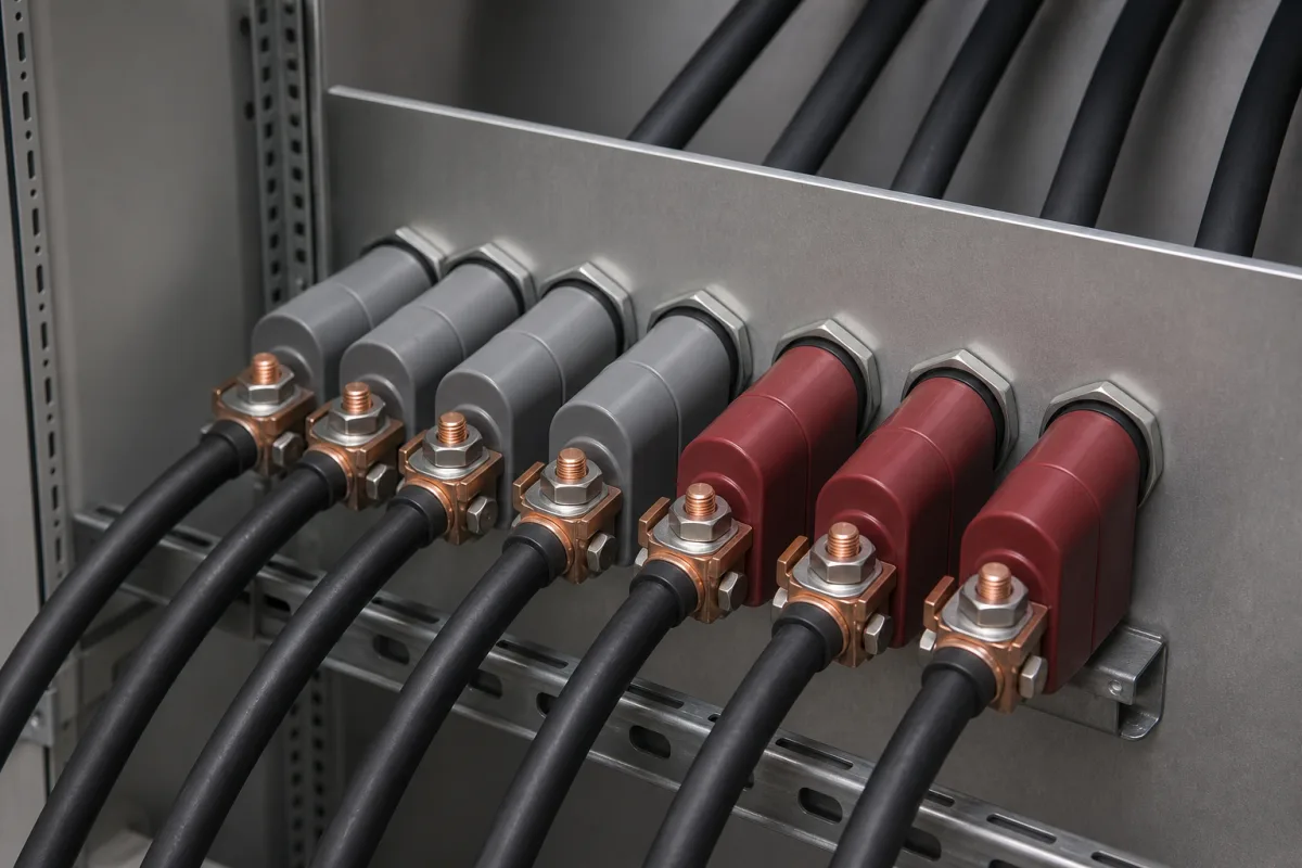
Representative product image. Confirm appearance and specifications with the manufacturer.

Product Specifications

Technical details and manufacturing context for Feed-through Terminal Blocks

Definition
Feed-through terminal blocks are specialized electrical connectors used within power line filter panels to provide secure wire termination points while allowing conductors to pass through the panel enclosure. They serve as the interface between incoming power lines and the filter components, ensuring proper electrical connections while maintaining panel integrity and safety. These terminal blocks feature conductive metal strips or bars enclosed in insulating housings. Wires are inserted into one side, secured with clamping mechanisms (screw terminals, spring clamps, or push-in), and pass through to the opposite side where they connect to filter components. This design allows for easy installation, maintenance, and isolation of electrical connections while preventing wire strain and maintaining proper spacing. The blocks are available in configurations with 2 to 12 positions, accommodating wire cross-sections from 0.5 to 16 mm². They are rated for continuous voltages up to 600 V and currents ranging from 10 to 65 A, depending on wire size and temperature. Insulation resistance is at least 1000 MΩ measured at 500 V DC, and dielectric strength is 2.5 kV for 50/60 Hz for 1 minute. Operating temperature ranges from -40°C to 85°C. Ingress protection varies from IP20 to IP65, with IP65 achievable when using a sealing cover. The housing material is typically thermoplastic (PA66 or PC) with a flammability rating of V-0 per UL 94. Contact plating is tin-plated copper alloy, and the conductive parts are made of copper alloy or nickel-plated steel. Tightening torque for screw terminals ranges from 0.5 to 1.2 N·m. Weight per position varies from 5 to 30 g. These values are reference ranges and must be verified for the specific model and application. Always consult the manufacturer's datasheet and relevant standards such as IEC 60947-7-1 and IEC 60529 for compliance and installation requirements.
Working Principle
Feed-through terminal blocks consist of a conductive metal strip or bar enclosed in an insulating housing. Wires are inserted into one side and secured by clamping mechanisms such as screw terminals, spring clamps, or push-in connections. The conductor passes through the block to the opposite side, where it connects to filter components. This design provides a secure electrical connection while allowing the wire to pass through the panel, maintaining panel integrity and preventing strain on the wire.
Common Materials
Copper alloy, Thermoplastic (PA66, PC), Nickel-plated steel
Technical Parameters
ParameterTypical rangeNotes & selection driver
Rated Voltage600 VMaximum continuous voltage per IEC standardIEC 60947-7-1
Rated Current10–65 ADepends on wire cross-section and temperatureIEC 60947-7-1
Wire Cross-Section0.5–16 mm²Solid or stranded copper wireIEC 60947-7-1
Number of Positions2–12 positionsCustom configurations available
Insulation Resistance≥1000 Measured at 500 V DCIEC 60947-7-1
Dielectric Strength2.5 kV50/60 Hz for 1 minuteIEC 60947-7-1
Operating Temperature-40–85 °CContinuous operationIEC 60947-7-1
Ingress ProtectionIP20–IP65IP65 with sealing coverIEC 60529
MaterialPA66Flammability rating V-0UL 94
Contact PlatingSnTin-plated copper alloy
Tightening Torque0.5–1.2 N·mFor screw terminalsIEC 60947-7-1
Weight5–30 gPer position, varies with size

Ranges are indicative industry figures for RFQ preparation, not a supplier commitment. Confirm every value and standard with the legal manufacturer before ordering.

Components / BOM
  • Terminal Housing Part
    Provides insulation and mechanical protection for conductive elements
    Material: Thermoplastic (PA66 with flame retardant)
  • Conductive Strip/Bar Part
    Carries electrical current between connection points
    Material: Copper alloy (tin-plated or silver-plated)
  • Clamping Mechanism
    Secures wires in place and ensures reliable electrical contact
    Material: Nickel-plated steel or brass
  • Mounting Foot/Bracket Part
    Allows secure attachment to the panel
    Material: Steel or thermoplastic

Applied To / Applications

This component is essential for the following industrial systems and equipment:

Industrial Ecosystem & Supply Chain Structure

Complementary Systems
Downstream Applications
Specialized Tooling

Application Fit & Sizing Matrix

Operational Limits
current: Up to 76A per pole (depending on wire size and terminal type)
voltage: Up to 600V AC/DC (UL/CSA rated)
ip rating: IP20 (standard), IP67/IP69K available for sealed versions
temperature: -40°C to +105°C (standard), up to +125°C (high-temp variants)
torque range: 0.5 Nm to 5.0 Nm (terminal dependent)
wire size range: 22 AWG to 250 kcmil (depending on model)
Media Compatibility
✓ Industrial control panels with EMI/RFI filtering requirements ✓ Power distribution systems with surge protection devices ✓ Motor control centers requiring line-to-ground filtering
Unsuitable: High-vibration environments without additional mechanical securing (e.g., heavy machinery without vibration dampening)
Sizing Data Required
  • Maximum continuous current per circuit (A)
  • Wire gauge range and conductor type (AWG/kcmil, solid/stranded)
  • Number of poles and required spacing/creepage distance for voltage class

Reliability & Engineering Risk Analysis

Failure Mode & Root Cause
Contact corrosion
Cause: Moisture ingress or chemical exposure leading to oxidation and increased electrical resistance at terminal connections.
Insulation breakdown
Cause: Thermal cycling, vibration, or mechanical stress causing cracks in insulating materials, potentially leading to short circuits or arcing.
Maintenance Indicators
  • Visible discoloration, charring, or melting around terminal connections indicating overheating
  • Audible buzzing, crackling, or intermittent arcing sounds from the terminal block during operation
Engineering Tips
  • Apply appropriate torque specifications during installation to prevent loose connections (which cause arcing) or overtightening (which damages terminals)
  • Implement regular infrared thermography inspections to detect abnormal heating patterns before catastrophic failure occurs

Indicative industry ranges for design and RFQ preparation. Confirm the exact figures and applicable standard with the manufacturer before specifying.

Compliance & Manufacturing Standards

Applicable Standards
IEC 60947-7-1: Low-voltage switchgear and controlgear - Terminal blocks for copper conductors UL 1059: Terminal Blocks DIN 46277-1: Flat plug-in connectors - Feed-through terminal blocks

Quoted from the published standard.

Manufacturing Precision
  • Bore diameter for conductor insertion: +/-0.05mm
  • Center-to-center spacing between poles: +/-0.1mm
Quality Inspection
  • Dielectric strength test (high-potential test) for insulation resistance
  • Pull-out force test for terminal clamping reliability

Manufacturers of Feed-through Terminal Blocks

3 companies list this product among what they make. Company figures are quoted from each company's own website; every card states where the relationship came from.

DEGSON
Zhejiang, CN
Listed on the company's own website · profile compiled by CNFX from public sources
Ningbo Forsent (Meigan) Electronics Co., Ltd.
Shanghai, CN
Also makes: Terminal Block
Listed on the company's own website · profile compiled by CNFX from public sources
Ningbo Max Electronic Technology Co., Ltd.
Zhejiang, CN
Also makes: Terminal Block
Listed on the company's own website · profile compiled by CNFX from public sources

Manufacturer listings support early research and capability understanding. They are not certification, ranking, or transaction guarantees.

Technical documentation
Request current drawings, revision history, and a signed specification sheet.
Manufacturing capability
Verify equipment lists, process limits, capacity, and representative production evidence.
Inspection readiness
Confirm test methods, calibrated equipment, sampling plans, and traceable reports.
Supplier transparency
Check the legal entity, factory address, ownership, certifications, and direct contacts.

CNFX does not score or rank suppliers. Buyers must verify all claims and documents with the legal manufacturer before ordering.

Supply Chain Compatible Machinery & Devices

Motor Terminal Block

A motor terminal block is a standardized electrical component that provides secure, insulated connection points for motor winding leads.

Explore Specs →
PLC Control System

A digital industrial computer control system that monitors inputs, makes decisions based on a custom program, and controls outputs to automate industrial processes.

Explore Specs →
Control Panel

A centralized interface for monitoring and controlling industrial equipment and processes

Explore Specs →
PLC Control Panel

A centralized interface unit housing the programmable logic controller and associated control components for industrial automation systems.

Explore Specs →

Frequently Asked Questions

What are feed-through terminal blocks used for?

They are used in power line filter panels to provide secure termination points for wires while allowing conductors to pass through the panel enclosure, connecting incoming power lines to filter components.

What are the typical electrical ratings?

Rated voltage up to 600 V, rated current from 10 to 65 A depending on wire cross-section and temperature, insulation resistance ≥1000 MΩ at 500 V DC, and dielectric strength of 2.5 kV for 1 minute.

What wire sizes can be accommodated?

Wire cross-sections from 0.5 to 16 mm² for solid or stranded copper wire. Always verify the specific model's wire range.

What standards apply?

Relevant standards include IEC 60947-7-1 for terminal blocks and IEC 60529 for ingress protection. Compliance must be verified with the manufacturer.

Data Basis

Editorial classification, named public sources where available, and source-reviewed manufacturer records.

Preliminary Technical Classification
This page supports structured research, RFQ preparation, and supplier evaluation. It does not replace buyer-led supplier qualification, standards review, or technical approval.
Buyer enquiry

Request manufacturing insight for Feed-through Terminal Blocks

Ask for use case, specification boundaries, supplier type, and RFQ preparation information for this product.

Where it goes
Straight to the CNFX editorial desk, and to the manufacturer if this product is linked to a claimed profile. Nothing is broadcast to a supplier list.
Your details stay here
We do not sell or rent enquiry data, and we do not add you to a mailing list. Used only to answer this request.
No commission, no middleman
CNFX is a directory. We take no cut of any order and never negotiate on a supplier's behalf.
What we don't claim
A listing is not an endorsement. Qualify every supplier and verify every figure yourself before ordering.

Your business information is used only to process this request.

Thank you! Your message has been sent. We'll respond within 1–3 business days.
Sorry, we couldn't send your message. Please try again, or email us at contact@cnfx.com.

Need to Manufacture Feed-through Terminal Blocks?

Compare manufacturer profiles with relevant product and process capability.

Previous Product
Electromagnetic Relay
Next Product
Filter Capacitor Bank
Get QuotesChat