Editorial Technical Reference

Clamping Mechanism

This page explains how Clamping Mechanism is classified within Machinery and Equipment Manufacturing. Technical values and manufacturer relationships are research references; confirm the current specification and supplier evidence for each order.

Technical Definition & Core Assembly

A mechanical device that securely holds tubes in place during bending operations to prevent movement and ensure precision.
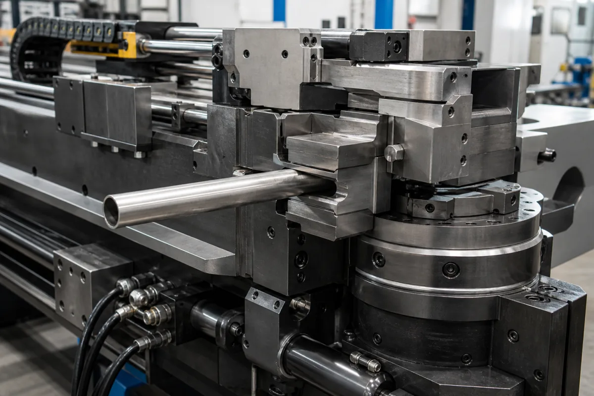
Representative product image. Confirm appearance and specifications with the manufacturer.

Product Specifications

Technical details and manufacturing context for Clamping Mechanism

Definition
The clamping mechanism is a critical component of industrial tube bending machines that firmly grips and immobilizes tubes at the bending point. It applies controlled pressure to prevent slippage, rotation, or deformation during the bending process, ensuring accurate angles, consistent radii, and maintaining tube integrity by minimizing unwanted stresses or marks on the workpiece. The mechanism typically uses hydraulic, pneumatic, or mechanical force to actuate clamping jaws or pads that contact the tube. Pressure is applied perpendicular to the tube axis, creating sufficient friction and mechanical interference to hold the tube stationary against the bending forces. Modern systems often incorporate sensors and feedback controls to adjust clamping force based on tube material, diameter, and wall thickness. Materials commonly used for the clamping surfaces include alloy steel, hardened tool steel, and carbide inserts, selected for wear resistance and durability. The clamping diameter range is typically from 5 mm to 300 mm, depending on the machine size. This range is a reference; the actual capacity must be confirmed for the specific model and application. When selecting or verifying a clamping mechanism, confirm the maximum clamping diameter, the actuation type (hydraulic, pneumatic, or mechanical), and the compatibility with the tube materials and wall thicknesses you process. Also verify that the clamping force is adjustable and that the mechanism includes any necessary sensors or feedback controls. Regular maintenance includes inspecting the clamping surfaces for wear, checking hydraulic or pneumatic seals, and verifying that the force adjustment system operates correctly. Failure to maintain proper clamping can lead to tube slippage, inaccurate bends, or damage to the workpiece. Always consult the manufacturer's documentation for model-specific specifications and safety guidelines.
Working Principle
The clamping mechanism operates by applying force perpendicular to the tube axis through jaws or pads. This force creates friction and mechanical interference that holds the tube stationary against the bending forces. The actuation can be hydraulic, pneumatic, or mechanical, and modern systems may use sensors to adjust the clamping force based on tube material, diameter, and wall thickness.
Common Materials
Alloy Steel, Hardened Tool Steel, Carbide Inserts
Technical Parameters

What to specify in your RFQ

  • Maximum clamping diameter range, typically from 5mm to 300mm depending on machine size in mm

These are the quantities to specify to the manufacturer when sizing or requesting a quote. The manufacturer's own documentation governs the exact figures and applicable standard.

Components / BOM
  • Clamping Jaws Part
    Direct contact surfaces that grip the tube, often with replaceable inserts for different tube materials
    Material: Hardened Tool Steel
  • Actuator
    Generates and transmits force to the clamping jaws (hydraulic cylinder, pneumatic piston, or mechanical linkage)
    Material: Steel Alloy
  • Pressure Plate Part
    Distributes clamping force evenly across the jaw assembly
    Material: Carbon Steel
  • Guide Rails Part
    Ensures precise linear movement of clamping components during opening and closing
    Material: Hardened Steel
  • Force Sensors Optional
    Measure clamping force so it can be trimmed to the tube material and wall thickness.

Applied To / Applications

This component is essential for the following industrial systems and equipment:

Industrial Ecosystem & Supply Chain Structure

Complementary Systems
Downstream Applications
Specialized Tooling

Application Fit & Sizing Matrix

Operational Limits
pressure: 0 to 10 bar
other spec: Tube OD range: 5-100 mm, Clamping force: 50-5000 N
temperature: -20°C to 150°C
Media Compatibility
✓ Stainless steel tubes ✓ Copper tubing ✓ Aluminum pipes
Unsuitable: Abrasive slurry environments with >20% solids concentration
Sizing Data Required
  • Tube outer diameter (OD)
  • Required clamping force
  • Bending radius to be applied

Reliability & Engineering Risk Analysis

Failure Mode & Root Cause
Thread wear and galling
Cause: Repeated cyclic loading causing metal-to-metal contact without proper lubrication, leading to thread deformation and seizing
Clamping force degradation
Cause: Material fatigue in clamping components from over-torquing or vibration-induced stress concentration, resulting in reduced holding capacity
Maintenance Indicators
  • Audible creaking or grinding noise during clamping/unclamping cycles
  • Visible misalignment or wobble in clamping components during operation
Engineering Tips
  • Implement torque-controlled tightening procedures with calibrated tools to prevent over-stressing components
  • Establish regular lubrication schedule using anti-seize compounds specifically formulated for threaded clamping mechanisms

Indicative industry ranges for design and RFQ preparation. Confirm the exact figures and applicable standard with the manufacturer before specifying.

Compliance & Manufacturing Standards

Applicable Standards
ISO 2768-1: General tolerances for linear and angular dimensions ANSI B18.2.1: Square and Hex Bolts and Screws DIN 6885: Clamping Elements for Shaft-Hub Connections

Quoted from the published standard.

Manufacturing Precision
  • Bore diameter: +/-0.02mm
  • Parallelism of clamping faces: 0.05mm
Quality Inspection
  • Dimensional verification with CMM (Coordinate Measuring Machine)
  • Torque testing for clamping force verification

Manufacturers of Clamping Mechanism

Manufacturer profiles associated with Clamping Mechanism.

Sourcing Clamping Mechanism from China?
Tell us your specification and target quantity — we will match it against manufacturer records and come back with the factories that fit.
Request manufacturers We manufacture this

Manufacturer listings support early research and capability understanding. They are not certification, ranking, or transaction guarantees.

Technical documentation
Request current drawings, revision history, and a signed specification sheet.
Manufacturing capability
Verify equipment lists, process limits, capacity, and representative production evidence.
Inspection readiness
Confirm test methods, calibrated equipment, sampling plans, and traceable reports.
Supplier transparency
Check the legal entity, factory address, ownership, certifications, and direct contacts.

CNFX does not score or rank suppliers. Buyers must verify all claims and documents with the legal manufacturer before ordering.

Supply Chain Compatible Machinery & Devices

Automated Powder Coating System

Integrated industrial system for applying dry powder coatings to metal substrates.

Explore Specs →
Centrifugal Pump Impeller

The centrifugal pump impeller is a critical rotating component that converts mechanical energy from the motor into kinetic energy in fluid systems.

Explore Specs →
High-Precision CNC Laser Cutting Machine

Computer-controlled industrial machine using focused laser beams to cut sheet metal with micron-level accuracy.

Explore Specs →
Industrial-Grade Hydraulic Cylinder Piston Rod

This industrial-grade piston rod is a precision-ground cylindrical component designed for use in hydraulic cylinders.

Explore Specs →

Frequently Asked Questions

What is the typical clamping diameter range?

The typical clamping diameter range is from 5 mm to 300 mm, depending on the machine size. This is a reference range; the actual capacity must be confirmed for the specific model and application.

What materials are used for clamping surfaces?

Common materials include alloy steel, hardened tool steel, and carbide inserts. These are selected for wear resistance and durability, but the specific material grade should be verified with the manufacturer.

How does the clamping force get adjusted?

The clamping force is adjusted based on tube material, diameter, and wall thickness. Modern systems may incorporate sensors and feedback controls to automatically adjust the force. Manual adjustment is also possible on some models.

What maintenance is required?

Regularly inspect clamping surfaces for wear, check hydraulic or pneumatic seals, and verify that the force adjustment system operates correctly. Follow the manufacturer's maintenance schedule for optimal performance.

Data Basis

Editorial classification, named public sources where available, and source-reviewed manufacturer records.

Preliminary Technical Classification
This page supports structured research, RFQ preparation, and supplier evaluation. It does not replace buyer-led supplier qualification, standards review, or technical approval.
Buyer enquiry

Request manufacturing insight for Clamping Mechanism

Ask for use case, specification boundaries, supplier type, and RFQ preparation information for this product.

Where it goes
Straight to the CNFX editorial desk, and to the manufacturer if this product is linked to a claimed profile. Nothing is broadcast to a supplier list.
Your details stay here
We do not sell or rent enquiry data, and we do not add you to a mailing list. Used only to answer this request.
No commission, no middleman
CNFX is a directory. We take no cut of any order and never negotiate on a supplier's behalf.
What we don't claim
A listing is not an endorsement. Qualify every supplier and verify every figure yourself before ordering.

Your business information is used only to process this request.

Thank you! Your message has been sent. We'll respond within 1–3 business days.
Sorry, we couldn't send your message. Please try again, or email us at contact@cnfx.com.

Need to Manufacture Clamping Mechanism?

Compare manufacturer profiles with relevant product and process capability.

Previous Product
Clamping Arm
Next Product
Clamping Units
Get QuotesChat