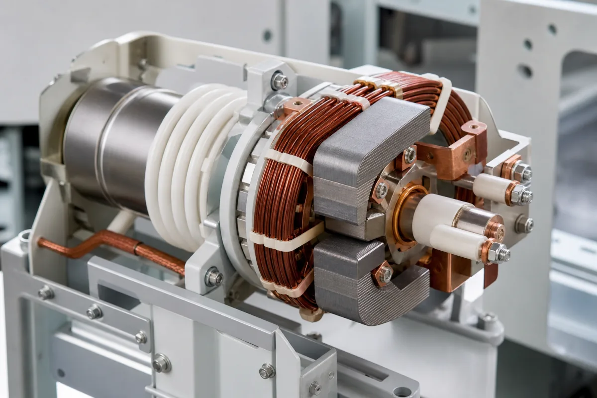
An axial magnetic field (AMF) coil carries the breaker's own current in loops so that, when the contacts part, a field runs along the arc instead of across it. That field turns a high-current arc that would otherwise contract into one spread evenly over the contact faces. The illustration shows the field source as a copper winding with laminated cores around the end of the interrupter; in production designs the coil is built into the contact assembly. This page is about sizing that field and paying for it.
Covers coils and coil-shaped current paths that produce an axial magnetic field in the contact gap of vacuum interrupters: field strength per kiloampere of peak current, field distribution and the contact-centre problem, impedance, heat rise, eddy currents and phase lag, one-sided and two-sided coil arrangements, and externally applied surrounding coils. The interrupter itself, its insulation, spiral (rotating-arc) contacts, erosion and vacuum integrity are on Medium-voltage vacuum interrupter. Laboratory Helmholtz coils and solenoids for magnetic testing are outside this page.
CNFX editorial research · Sources checked October 12, 2026 · 3 sources
Eaton's patent US 5,691,522 (Schulman and Slade) states the job of the field: force an initially columnar high-current vacuum arc to become diffuse and spread through the gap, so the anode becomes a passive collector of diffuse current, which gives the device its interruption ability.
The patent uses a minimum acceptable field as the design criterion. At peak current Im in kiloamperes, the axial field Ba in millitesla over the larger part of each contact face should satisfy 5 × Im > Ba ≥ 3.2 × (Im − 9). A field larger than needed adds complexity, cost, impedance, heat and eddy currents, so the aim is the bottom of the window, not the top.
It checks the rule against a published slotted-cup design (contact radius 41.5 mm, gap 15 mm, six slots): 4.2 mT per kA at the gap centre from both contacts, above that design's own stated minimum of 3.5 mT per kA. Its own one-sided example is rated for about 51 kA peak with a gap up to about 12.8 mm.
Rated short-circuit current (rms)
Peak Im = √2 × rms
Minimum Ba = 3.2 × (Im − 9)
Upper bound 5 × Im
25 kA
35.4 kA
≈85 mT
≈177 mT
31.5 kA
44.5 kA
≈114 mT
≈223 mT
40 kA
56.6 kA
≈152 mT
≈283 mT
51 kA peak (patent example)
51 kA
≈134 mT
≈255 mT
Editorial calculation from the patent's relation, using its own √2 conversion from rms; the rated currents are illustrative. The patent ignores radial variation of the field; ask for the measured or modelled field at the gap centre and at the contact face, at full gap and at peak current.
02
Impedance, heat rise and eddy-current lag
The same patent lists what the coil costs. AMF contact assemblies are harder and dearer to make than plain contacts, add impedance against the goal of a low-impedance interrupter, and so add heat rise during normal current conduction. Part of that heat comes from eddy currents that the alternating field induces in the conducting parts; those eddy currents also cut the net field and add a phase delay between field and current, and the patent notes that methods for suppressing them can add complexity to the contact geometry.
Eaton's answer is asymmetric: an AMF assembly behind only one contact, built as an annular coil of N segments carrying equal branch currents, with a small leakage path. That lowers complexity, cost, impedance, heat and eddy currents against designs that put a coil on both sides. The trade is that the field is no longer symmetric about the gap centre; it falls steadily with distance from the coil side.
Arrangement
Field across the gap
Penalty
Coil behind both contacts
Symmetric about the gap centre
Two coils' impedance, heat and eddy currents
Coil behind one contact (US 5,691,522)
Highest at the coil side, falling across the gap
Coil must be sized so the far contact still meets the minimum
Ask for the coil's contribution to the interrupter's main-circuit resistance, the temperature rise at rated normal current, and the phase lag between field and current at the expected current-zero.
03
Keeping the contact centre from burning
Hitachi's patent US 4,430,536 (Kurosawa et al.) describes the coil electrode in detail and a failure it can cause.
Each composite electrode carries a main contact with a coil electrode behind it: arm conductors take current radially out from the central rod and circumferential conductors turn it into loops concentric with the rod. The two electrodes are mated so the fields of the radial currents, which flow in opposite directions on the two sides, cancel, leaving the axial field from the loops, which run the same way on both sides. The field disperses the arc into countless fine fibre-like segments.
The problem the patent addresses is that with a strong parallel field the arc can stop spreading to the rim and collapse onto the centre of the contact face, which is then badly fused and the interruption fails. Its fix is a projecting piece of high-conductivity material at the centre of the contact: eddy currents in it partly cancel the field there, so the arc moves outward to where the field is stronger.
Ask how the field is distributed radially across the contact face and whether the contact centre is shaped or slotted to control it.
04
An external surrounding coil
A coil wound around the outside of the interrupter, as drawn in the illustration, is the arrangement studied by Jadidian, Niayesh and Hashemi (University of Tehran) in J. Plasma Fusion Res. Series vol. 8 (2009).
The paper notes that AMF is used across vacuum interrupters to keep the arc diffuse, and that a stronger field extends the multiple-arc (diffuse) mode to higher currents. Fields in earlier work stayed below hundreds of millitesla, with about 1.2 T as the highest reported; the obstacle to more is the size of the capacitor banks needed to drive a separate coil.
The authors propose a helical inductor tightly surrounding the chamber, driven by cascaded flux-compression generators fed from the fault current itself through current transformers with a 1:1 ratio used only to separate the circuits. In their simulation a 150 kA fault current is multiplied to about 1 MA, giving a field of the order of 10 T inside the chamber, and arcs up to 200 kA stay diffuse. This is a modelling study, not a tested product.
Editorial reading: an external coil must push its field through the interrupter's metal end caps and shields, where eddy currents oppose it, which is the same lag and loss problem described above. Treat a surrounding-coil design as special; ask for test reports at rated short-circuit current rather than simulated field values.
05
What to ask about an AMF coil or AMF contact assembly
Paste it into your enquiry below or into an email to a maker, then replace every bracket.
Give the rated voltage, rated short-circuit breaking current (rms and peak), rated normal current and the open contact gap. Ask for the axial field per kA at the gap centre and contact face at peak current and full gap, the coil arrangement (one-sided, two-sided or external), the added resistance and temperature rise at rated current, the field-to-current phase lag, and short-circuit type-test reports for the interrupter fitted with that coil.
Explore company information and manufacturing capabilities, then discuss the scope of your project with a relevant supplier.
Share this page
Compiled and source-reviewed by the CNFX editorial team.
Each manufacturer above links to the page on that company's own website where the product is listed, with the date we checked it. How we source and review
· Page last updated 13 October 2026
Buyer questions
How strong should the axial magnetic field be?
Eaton's patent gives 5 × Im > Ba ≥ 3.2 × (Im − 9), with Ba in mT and peak current Im in kA. For a 40 kA rms rating that is a minimum of about 152 mT (Editorial calculation). [1]
Why not make the field as strong as possible?
A larger field than needed brings more complexity, cost, impedance, heat rise and eddy currents, according to Eaton's patent. Hitachi's patent also describes a strong field collapsing the arc onto the contact centre. [1][2]
What do eddy currents do to the field?
They reduce the net axial field and delay it relative to the main current, and they add to heat rise during conduction. [1]
Can the coil sit outside the interrupter?
A University of Tehran simulation studied a helical coil surrounding the chamber, driven by flux-compression generators, reaching about 10 T; it is a modelling study, not a commercial design. [3]
Sources and what still needs a direct check
Sources checked 2026-10-12. Two vacuum interrupter patents from different makers and a peer-reviewed plasma-research paper.