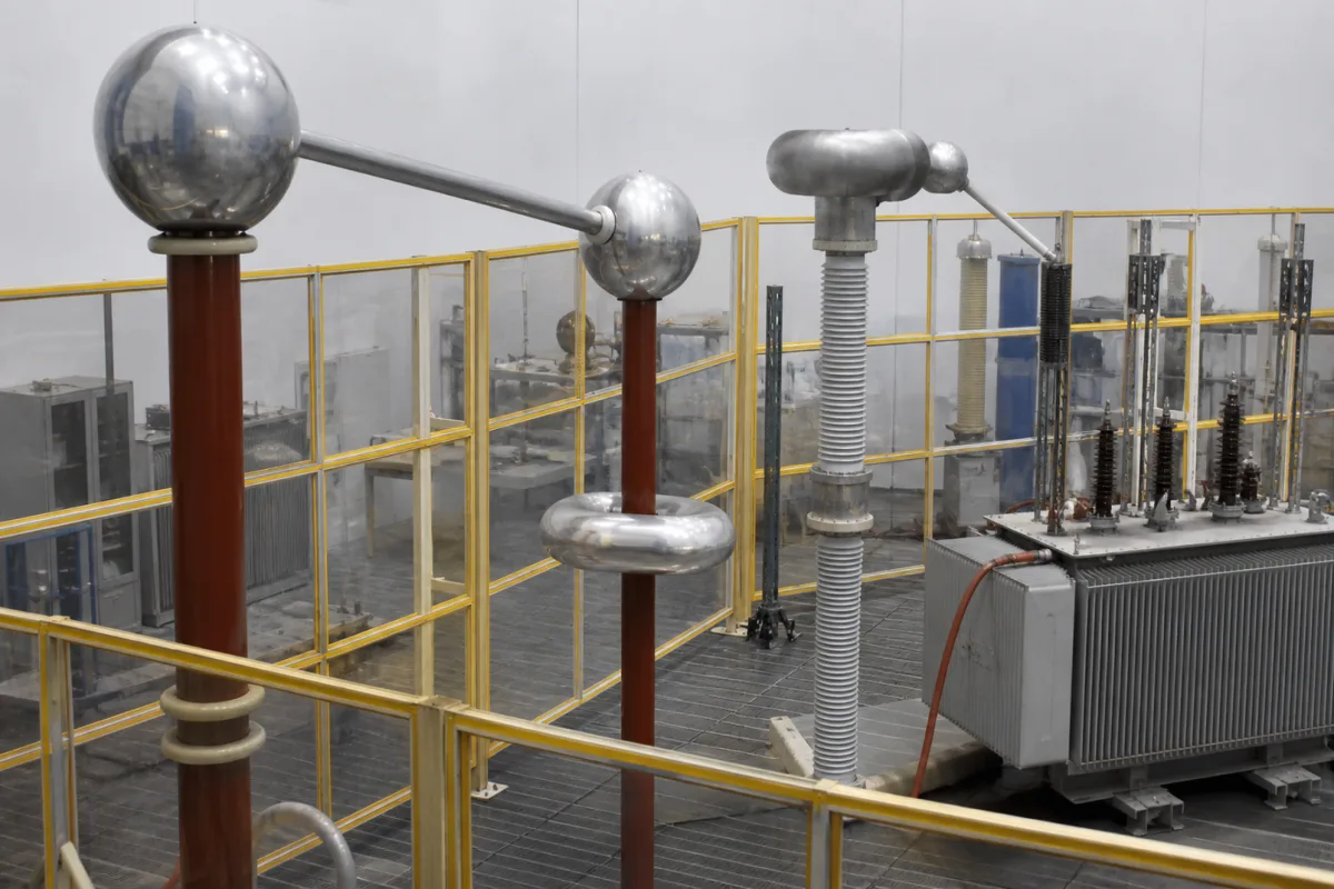
Test electrodes for a high-voltage laboratory circuit: corona-free top electrodes, connecting cups and rods, and the sphere, rod and needle electrodes of a measuring gap
Corona-free spheres, cups, rods and gap electrodes in a modular AC test circuit · 300 mm and 800 mm top electrodes · a 9.3 cm sphere radius for 200 kV
In a laboratory test circuit the conductor between the transformer, the divider, the gap and the test object is not a wire: it is a chain of aluminium spheres, cups, rods and domes, each sized so that it does not itself go into corona below the test voltage. A buyer specifying these electrodes needs the diameter and radius of each piece against the highest voltage it will carry, how the pieces plug together, and which shapes the measuring gap needs.
Metal electrodes that make up the high-voltage side of a laboratory AC, DC or impulse test circuit: corona-free top and shielding electrodes on transformer stages and dividers, connecting cups and connecting rods that join modular components, termination electrodes used with earthing switches, and the interchangeable sphere, rod, needle and plane electrodes of a measuring or impulse spark gap. The tester that applies a withstand voltage to a product is covered on the Dielectric strength (hipot) tester page, and the walk-in earthed cell in which single switchgear components are tested on the High-voltage test chamber for switchgear components page. Electrodes that clamp a sheet or film specimen for breakdown-strength testing of insulating materials, and spheres and domes for HVDC converter halls as installed station hardware, are outside this page.
CNFX editorial research · Sources checked October 13, 2026 · 3 sources
Connecting cups, connecting rods and top electrodes: how Terco's 100 kV modular set is joined and shielded
Terco's HV9000 training set builds the high-voltage side out of plug-together aluminium pieces. Its HV9105 test transformer, rated 100 kV and 10 kVA with partial discharge of 5 pC or less at rated voltage, carries top and bottom corona-free aluminium shielding electrodes, and the other parts connect through cups and rods. [1]
The fixed 743 mm rod and the cup's six sockets set the geometry of the circuit: components stand one rod length apart and meet at a cup. The 800 mm electrode is reserved for the top of a three-stage cascade, while a single 300 mm electrode serves as the termination at the earthing switch. [1]
Terco gives diameters and weights but no corona-inception voltage for the individual electrodes; its corona statement is attached to the transformer, at 5 pC or less at 100 kV. [1] When buying electrodes separately, ask the supplier for the voltage up to which each piece has been checked free of corona in the intended arrangement.
Terco part
What it does
Published size
HV9140 Electrode 300
Top electrode on the top transformer of a three-stage AC set-up, polished aluminium [1]
List every node in the circuit (transformer top, divider top, gap, test object, earthing point), the highest voltage at each, and the socket arrangement needed, so cups, rods and electrodes can be matched to it.
02
Radius of curvature against corona: a connecting sphere redesigned from 114.2 kV onset to no corona at 200 kV
In Aalborg University's 200 kV laboratory set-up, partial-discharge tests located the lowest corona onset not on the transformer but on the aluminium connecting sphere between transformer and capacitive divider: 114.2 kV, with corona clearly audible at 131.2 kV, against 148.9 kV at the transformer's top electrode. The existing sphere had a radius of 7.5 cm and sharp edges with a much smaller radius of curvature. [2]
The 2013 master's thesis sized a replacement with the streamer criterion, aiming for corona onset at 220 kV, a 10 % margin over the 200 kV target, and looking for a criterion value K between 18 and 20; the radii tried are listed in the table in the order calculated. [2]
The sphere was built in the university workshop at 9.3 cm radius, hollowed and flattened underneath to sit on the divider, with a recess on top for a connecting rod of the same diameter as the existing one. Editorial calculation: 9.3 cm radius is a sphere about 186 mm across, against 150 mm for the old 7.5 cm sphere. [2]
After the change, partial discharge first appeared at 149.3 kV and was traced to the transformer; an ultrasound detector picked up no sound from the new sphere at 200 kV and no visible corona was seen on it in a darkened hall. The thesis notes that its partial-discharge instrument could not separate the sphere from the transformer above 149 kV, so the 200 kV result rests on the acoustic and visual checks. [2]
State the highest rms or peak voltage each electrode will carry and the margin wanted above it, and ask how the supplier verified corona-free operation: partial-discharge level, acoustic or UV inspection, and in what arrangement.
03
Sphere, rod, needle and plane electrodes for a measuring spark gap and an impulse sphere gap
A spark gap is the other place where electrodes are bought as a set. Terco's HV9133 measuring spark gap, for 100 kV rms AC and 140 kV DC and impulse, is a standard measuring device for flashover voltage with remote and hand-operated gap setting, supplied with five electrodes in a fitted case: spheres of 50 and 100 mm diameter, a 20 mm rod, a needle and a flat electrode. [1]
For impulse generation the HV9125 sphere gap presets the impulse peak: 140 kV impulse with 100 mm spheres, gap settings up to 80 mm and a gap-setting indicator, 743 mm long, 7 kg; the HV9126-D drive adjusts it. An electronic trigger sphere, HV9132, can be mounted on the HV9133 to use it as a triggered spark gap. [1]
Swapping spheres for rod, needle or plane pieces changes the field shape on the same gap. Aalborg's thesis works through rod-to-plane and coaxial-cylinder examples, and shows the field concentrating around a hemisphere of 0.2 cm radius added to the inner cylinder at 20 kV, since the field becomes stronger with a smaller radius. [2]
Specify sphere diameters, the other electrode shapes needed, maximum gap, how the gap is set and read, and whether it must be triggered.
04
Why diameters keep rising with voltage: ABB on 1.3 m and 1.8 m spheres and the limit of saturation
ABB's US patent 9,343,892 (2016) describes the same problem at station scale: electrodes with large radii of curvature are used so that the point is free of corona and meets the breakdown requirement for the voltage level. For valve-hall interconnections, it states, the spherical electrodes of initial HVDC projects were 1.3 m in diameter and 800 kV DC projects use 1.8 m or more. [3]
The patent adds that diameter does not buy withstand in proportion: the increase in diameter is not directly proportional to the increase in gap factor or withstand voltage, and research it cites found that for 1,100 kV DC a 2 m sphere with 15 m or more of insulation distance could not meet the minimum 50 % switching-impulse withstand because the gap saturates. Its proposal is a mushroom-shaped electrode instead of a larger sphere. [3]
The Aalborg redesign made the same trade at laboratory scale: it took the smallest radius that met its criterion rather than the 10 cm first guess, noting that a larger margin, such as onset at 250 kV, would mean a larger sphere and more material cost. [2]
Give the hall dimensions and the distance from each electrode to walls, floor and earthed structures along with the voltage, so electrode size is chosen for the actual clearance.
05
Data for laboratory test-circuit electrodes
Paste it into your enquiry below or into an email to a maker, then replace every bracket.
Circuit: [AC / DC / impulse; number of stages; highest voltage kV rms or peak]
Nodes: [transformer top, divider top, gap, test object, earthing switch]
Pieces: [top electrodes Ø mm; connecting cups and socket layout; rods length; flexible leads]
Corona-free level: [voltage and PD limit or acoustic/UV check required]
Spark gap: [sphere Ø 50/100 mm or other; rod, needle, plane; max gap; drive and indicator; trigger]
Material and finish: [aluminium, polished; weight limits on insulator columns]
Hall: [distance to walls, floor and earthed structures]
Explore company information and manufacturing capabilities, then discuss the scope of your project with a relevant supplier.
Share this page
Compiled and source-reviewed by the CNFX editorial team.
Each manufacturer above links to the page on that company's own website where the product is listed, with the date we checked it. How we source and review
· Page last updated 13 October 2026
Buyer questions
What sizes are the electrodes in a modular 100 kV laboratory set?
Terco lists an 800 mm top electrode for a three-stage AC set-up, a 300 mm termination electrode, a 157 mm connecting cup and a 743 mm connecting rod. [1]
How large does a connecting sphere need to be to stay corona-free at 200 kV?
In Aalborg University's set-up a 9.3 cm radius sphere, sized by the streamer criterion for 220 kV, showed no acoustic or visible corona at 200 kV, where the old 7.5 cm sphere had started at 114.2 kV. [2]
Which electrodes come with a measuring spark gap?
Terco's HV9133 comes with 50 mm and 100 mm spheres, a 20 mm rod, a needle and a flat electrode, for 100 kV rms AC and 140 kV DC and impulse. [1]
Does a bigger sphere always raise the withstand voltage?
No. ABB's patent states that withstand does not rise in proportion to diameter and that the gap saturates; at 1,100 kV DC a 2 m sphere could not meet the switching-impulse requirement. [3]
Sources and what still needs a direct check
Sources checked 2026-10-13. Terco's product pages for its HV9000 modular high-voltage set (electrodes, cups, rods, spark gaps and the transformer they sit on), the 2013 Aalborg University master's thesis that measured and redesigned a corona-prone connecting sphere in a 200 kV set-up, and ABB's US patent on high-voltage electrodes for HVDC valve halls.