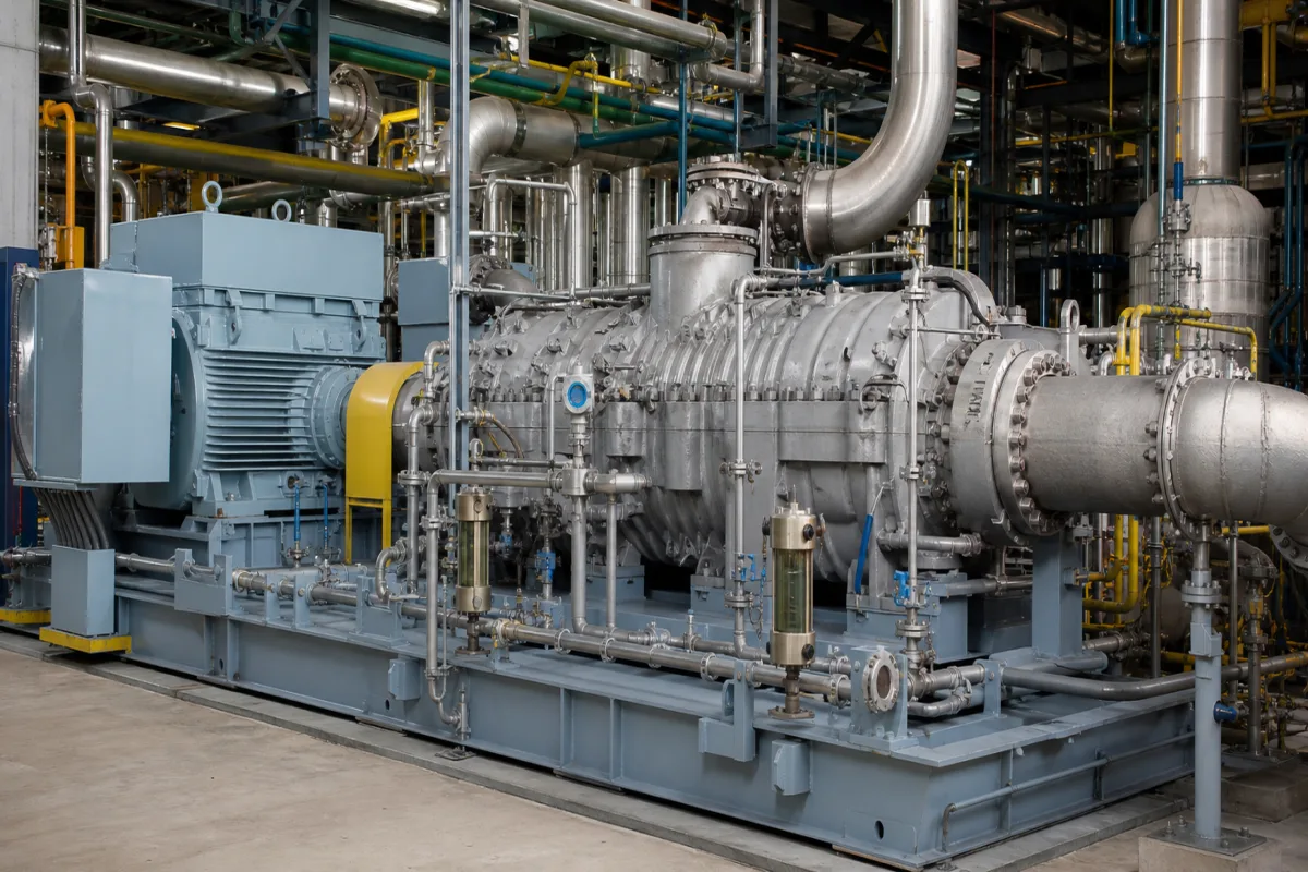
Ammonia synthesis gas compressors · Barrel-type (vertically split) multi-stage centrifugal compressors raising hydrogen–nitrogen syngas to loop pressure in LP and HP casings, driven by steam turbine or electric motor with speed-increasing gears, with dry gas seals and impeller material limits for hydrogen service
The synthesis gas compressor raises the hydrogen–nitrogen gas of an ammonia plant to the high pressure of the synthesis loop, and it sets the plant's production capacity. It is a multi-stage centrifugal machine in barrel casings, driven by a steam turbine or an electric motor. Ask three things first: what flow, suction and loop pressures and gas composition the train must handle, how the LP and HP casings and the driver are arranged, and which seal, material and maintenance requirements apply.
Centrifugal synthesis gas (make-up and recycle) compressors for ammonia plants, with their casings, impellers, seals, drivers and gears. Air compressors (see air compressor), refrigeration and CO2 compressors, centrifugal fans and pumps are outside this page.
CNFX editorial research · Sources checked October 12, 2026 · 4 sources
MHI Compressor describes the synthesis gas compressor as the heart of an ammonia plant, directly affecting production capacity. Because synthesis needs high pressure and the suction-to-discharge pressure ratio is high, at least two compressors are needed, one low-pressure (LP) and one high-pressure (HP). For this high-pressure service it uses vertically split (V-type) single-shaft multi-stage compressors with a barrel-type outer casing that it says can withstand about 50–700 barg, and up to 1,000 barg experimentally; in this service they have been used at 150–300 barg. [1]
Maintenance is by pulling the compressor internals out along the shaft axis; MHI uses a boltless end closure with shear and retaining rings to shorten disassembly and remove leak paths around bolts. It also compares its train arrangement with conventional single-end-drive series trains in which the inner compressor must be removed for maintenance. [1]
MHI reports more than 350 compressor units supplied to ammonia plants since the 1960s, including one of the largest plants at 3,600 tonnes per day. [1]
Give the supplier the plant capacity, syngas composition and molecular weight, flow, suction and discharge pressures and temperatures for LP, HP and recycle duties, intercooling, driver preference (steam conditions or electrical supply), seal system requirements, applicable standards, site conditions, and whether it is a new train or a revamp on existing foundations.
02
Choose the driver, seals and impeller materials
MHI matches compressor speed to the steam turbine for efficiency and smaller casings. For motor-driven trains, increasingly used, a 4-pole 60 Hz motor runs at a fixed 1,800 rpm, so it places speed-increasing gears between a double-ended motor and each of the LP and HP compressors to set each compressor's speed. In green ammonia plants with no reformer steam, it says the driver changes from steam turbine to electric motor and a booster compressor is needed to mix electrolytic hydrogen with nitrogen. [1]
Dry gas seals with a 2–3 µm gap between rotating and stationary rings need a seal gas supply unit delivering filtered clean gas; MHI offers this unit mounted detachably on the compressor base plate so piping can be checked before shipment. [1]
MHI's patent US11788546 describes a train in which a steam turbine sits between and drives the LP and HP compressors, and claims impellers whose maximum tip speed is 290–390 m/s while the impeller material has a yield strength of at most 827 MPa and a Brinell hardness of at most 311. [2]
Editorial calculation: a 4-pole motor on 60 Hz turns at 60 × 60 × 2 ÷ 4 = 1,800 rpm, matching MHI's figure. [1]
03
Tie compressor duty to the synthesis loop conditions
Fertilizers Europe's BAT booklet No. 1, Production of ammonia (2000 edition), states that synthesis gas production and purification take place at 25–35 bar, while ammonia synthesis on an iron catalyst runs at 100–250 bar and 350–550 °C. Modern plants use centrifugal compressors for synthesis gas, driven by steam turbines with steam raised in the ammonia plant, and the refrigeration compressor that condenses product ammonia is driven by a steam turbine as well. [3]
The booklet recommends adding make-up gas after ammonia condensation and ahead of the converter, with purge taken after ammonia separation and before make-up addition; this needs the make-up gas to be dried first, otherwise it must enter before condensation, with penalties for condensation and energy. Because only 20–30% reacts per pass, the recycle stage of the compressor circulates the unreacted gas back to the converter. [3][1]
Editorial calculation: compressing from 25–35 bar to 100–250 bar is an overall pressure ratio of about 2.9 to 10, consistent with the need for more than one casing; a 1,500 t/d plant produces about 62.5 t of ammonia per hour.
Loop item (Fertilizers Europe booklet)
Value
Synthesis gas production and purification pressure
25–35 bar
Ammonia synthesis pressure
100–250 bar
Synthesis temperature
350–550 °C
Conversion per pass
20–30%
Inerts held in loop by purge
About 10–15%
Large single-train plant size
1,000–1,500 t/d (1,800 t/d and above in new plants); 1,500 t/d used as standard
Energy use of a modern steam-reforming plant
40–50% above thermodynamic minimum, more than half of the excess from compression losses
State plant capacity, make-up gas pressure and composition, loop pressure, whether make-up gas is dried, and the driver (steam turbine or motor), and ask for the compressor's stage split between make-up and recycle duty.
04
Check vendor efficiency and power against published plant-model assumptions
An open-access techno-economic study by Zecca and co-authors (Energy & Fuels, 2025) models ammonia plants in Aspen Plus and assumes a polytropic efficiency of 0.75 for process air, syngas, NH₃ synthesis and CO₂ compressors in small-scale plants and 0.85 in large-scale plants, with mechanical efficiency fixed at 0.95 for all equipment. It states that large-scale plants drive major compressors with steam turbines using steam generated on site, while its small-scale plants drive all equipment electrically from the grid. [4]
The study sizes a 4-stage intercooled compressor, cooled to 15 °C with stage polytropic and mechanical efficiencies of 0.85 and 0.95, to raise membrane permeate to 312 bar, which it gives as the design pressure of the gas sent to its ammonia synthesis loop; the loop feed is 3,368 kmol/h of H₂ and 1,123 kmol/h of N₂. It describes the syngas compressor in these plants as a centrifugal compressor as used in ammonia plants. [4]
For cost it scales equipment as C = n × C₀ × (S/(n × S₀))^f, with a reference compressor cost of 10.17 M€ at 15.3 MW and f = 0.67, updated with the June 2024 CEPCI of 798.8. Editorial calculation: on that curve a single 30 MW compressor comes to about 10.17 × (30/15.3)^0.67 ≈ 16.0 M€, and the stated loop feed gives an H₂:N₂ ratio of 3,368/1,123 ≈ 3.0. These are study-level estimates, not quotations. [4]
Find ammonia synthesis gas compressor manufacturers
Ask any supplier for casing type and design pressure, number of stages and casings, impeller tip speed and material, performance curves for LP, HP and recycle duties, driver and gear selection, seal and seal gas system, bearing and rotor dynamics data, applicable standards, references, foundation loads and maintenance method.
06
Casing, impeller, gear and seal roles in a two-casing train
Impeller tip speed and material limits come from MHI's patent claim; the casing, gear and seal roles come from its product description.
Part
Role
Fix in the order
Barrel (V-type) casing
Contains high-pressure gas; internals pull out axially. [1]
Flow, power and temperatures the compressor vendor still has to supply
The reviewed sources state pressures, motor speed, assumed efficiency and impeller limits; flow, shaft power, inlet and discharge temperatures, noise, vibration and weight have to come from the vendor's duty sheet for each casing.
Field
What it means and published values
Ask the supplier for
Operating Pressure (bar)
e.g. 150–300 barg in this service; casing about 50–700 barg. [1]
Explore company information and manufacturing capabilities, then discuss the scope of your project with a relevant supplier.
Share this page
Compiled and source-reviewed by the CNFX editorial team.
Each manufacturer above links to the page on that company's own website where the product is listed, with the date we checked it. How we source and review
· Page last updated 13 October 2026
Buyer questions
Why do ammonia plants use two syngas compressors?
MHI says the high suction-to-discharge pressure ratio needs at least an LP and an HP compressor. [1]
What casing type handles synthesis loop pressure?
MHI uses vertically split barrel casings, used at 150–300 barg in this service. [1]
How are motor-driven syngas compressors sped up?
MHI places speed-increasing gears between a double-ended motor and each compressor. [1]
What pressure does the ammonia synthesis loop run at?
Fertilizers Europe's BAT booklet gives 100–250 bar and 350–550 °C for synthesis, with synthesis gas produced at 25–35 bar. [3]
What polytropic efficiency do ammonia plant models assume for syngas compressors?
One 2025 Energy & Fuels study assumes 0.75 for small-scale plants and 0.85 for large-scale plants, with 0.95 mechanical efficiency; ask the vendor for guaranteed values. [4]
Sources and what still needs a direct check
Sources checked 2026-10-12. Mitsubishi Heavy Industries Compressor makes synthesis gas compressor trains and holds a related patent; Fertilizers Europe's BAT booklet gives synthesis loop conditions, and an open-access Energy & Fuels plant study gives the compressor efficiency and cost assumptions it modelled.