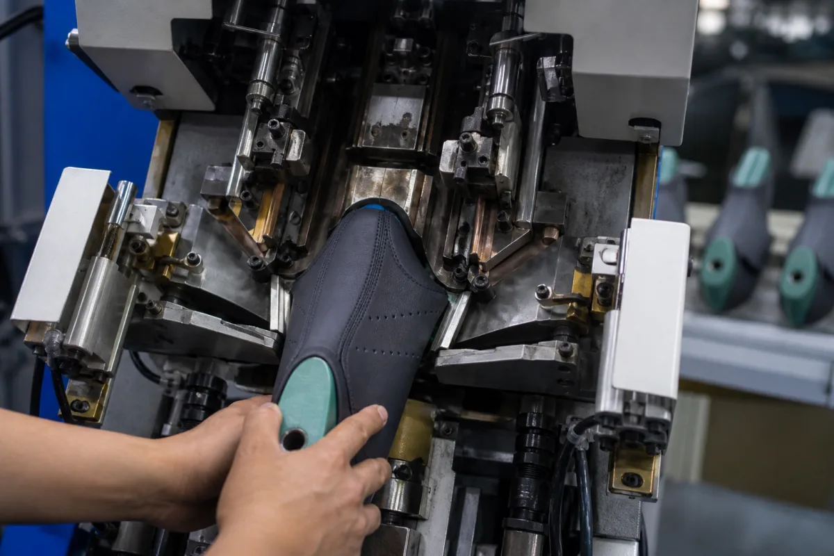
Industrial footwear upper stretching machine (pulling-over and toe lasting machine)
Pulling-over and toe lasting machines that stretch shoe uppers over the last · Toe and side pincers in a U around the shoe support, upward stretching, pincer height adjustment, wipers pressing the margin onto the insole, cycle stages and stops, and setting pincers for shoe width
An upper stretching machine for footwear, known in the trade as a pulling-over and toe lasting machine, grips the edge (lasting margin) of a shoe upper fitted on a last, stretches it tight over the toe of the last and then wipes the margin over and presses it onto the insole. It sets the toe shape and fit of the shoe. Ask three things first: which lasts, sizes and upper materials it must handle, how its pincers are arranged and adjusted for different widths, and how the stretch, wiping and stops in the cycle are controlled.
Pulling-over and toe lasting machines for shoe uppers on lasts, including their pincers, shoe support, wipers and controls. Side and seat lasting machines, upper pre-forming or moulding machines, cementing and heat-setting equipment, and lasts themselves are outside this page except where compared.
CNFX editorial research · Sources checked October 11, 2026 · 4 sources
US patent 4,193,154 (Toe pulling over and lasting machine, 1980) describes the established machine, which works on a shoe assembly made of a last with an insole on its bottom and an upper mounted on it. A support holds the shoe bottom-down; a toe pincer grips the upper margin near the toe end, and at least one side pincer on each side grips the margin further back. Upper-stretching means move the support upward relative to the pincers to stretch the toe portion of the upper about the last, and optional pincer adjusting means then set each pincer's height to relocate the stretched upper on the last. [1]
US patent 4,688,288 (Pulling over and toe lasting machine, 1987) describes such machines as having a toe pincer and two sets of side pincers arranged in a U-shape about the shoe support, gripping the lasting margins and tensioning the upper about the last. Each pincer can be adjusted lengthwise and widthwise for the shoe size and style, but it reports that operators set the side pincers only to the largest shoe to avoid time-consuming adjustment, which does not give the best lasting result. Its machine mounts each set of side pincers on a pivoting support moved equidistantly in or out to pre-set positions for different shoe widths. [2]
Editorial note: send the supplier your last range and upper materials, and ask how pincer positions are set for each size and width and how quickly they change over.
Give the supplier the shoe types, last sizes and width fittings, upper materials and thicknesses, insole type, the lasting adhesive and how it is applied, number and layout of pincers wanted, pincer height and width adjustment method, stretch force control, wiper type, cycle control and stops, production rate, changeover time between sizes and styles, and operator safety requirements.
02
Control wiping and the cycle stages
In the machine described in US 4,193,154, wipers wipe the toe portion of the upper margin against the insole. The cycle runs in stages: a preliminary stage in which the toe pincer grips the margin, a primary stage in which the side pincers grip and the stretching means act, and a secondary stage ending with the wipers. A treadle (pedal) control starts each stage, and a selector decides whether the machine halts after the primary stage so the operator can adjust the pincers, or runs straight through; the patent adds a three-position selector to choose where the machine halts. [1]
US 4,688,288 describes the wiper assembly as two wiper plates placed symmetrically either side of the machine's centre line, which wipe the tensioned lasting margin over and press it against the insole margin. [2]
Editorial note: ask the supplier to demonstrate the stop points in the cycle and the wiping pressure setting on your shoes, since operators need to correct the upper position before wiping.
03
Compare a single toe laster with a combined toe, side and heel machine
International Shoe Machine Corporation's US patent 5,678,269 (filed 2 February 1995, granted 21 October 1997) describes the process it set out to shorten: a footwear assembly is toe lasted, then heel lasted, then side lasted on two or three different machines, each with its own operator and training. It adds that the operator's manipulation of the shoe on these machines demands extensive wrist movement and has been known to lead to carpal tunnel syndrome. [3]
Its machine lasts toe, sides and heel in one station. In the preferred embodiment up to eleven pincer assemblies take the toe and ball portions of the upper margin: the operator slides the upper into one to three centre pincers and presses a two-stage foot pedal to close them, then feeds the rest and presses to the second stage to close all pincers. For safety the automatic cycle starts only after the operator presses two palm buttons, and a programmable controller sequences the cycle from proximity sensors and switches through solenoid valves supplying compressed air to the cylinders. [3]
After stretching, a toe clamping band holds the upper, the toe and ball wipers press the margins onto the insole against an overhead toe hold-down locked by a brake, a sensor sets the heel wiper height relative to the insole, a three-part heel clamping pad clamps the heel, and the heel and shank are then wiped progressively; the heel post is screw-driven to change the toe-to-heel distance for each size range. [3] Editorial note: if you compare a combined machine with separate toe and heel lasters, ask each supplier for the number of pincers, the size range per set-up, the start-safety arrangement (palm buttons or equivalent) and the cycle time per pair on your lasts.
04
Check that the upper material can take the lasting stress
Harnagea and Secan (Annals of the University of Oradea) state that lasting uppers involves tensile stresses of about 7–8 N/mm². They tested sports-shoe upper leathers and warp-knitted spacer fabrics on a SATRA STM 466 tester, reading elongation at an imposed 10 N/mm² after conditioning at 20 ± 2 °C and 65 ± 2% humidity for 24 hours. [4]
The authors conclude that two of the spacer fabrics cannot be used alone and need leather reinforcement in the forepart, heel or sides, that one fabric resists only 7 N/mm², and that the nubuck and spacer fabric combination will resist the lasting process. [4] Editorial note: send the supplier samples of each upper and lining combination you will last, and ask for trials on the machine offered at your pincer and stretch settings.
Shoe support, toe and side pincers, width pre-sets, wiper plates and cycle controls
Pincer adjustment is where the two older patents differ: US 4,193,154 re-sets pincer height after the stretch, while US 4,688,288 adds pre-set width positions so side pincers are not left at the largest shoe's setting. [1][2]
Two-stage pedal, two palm buttons, programmed cycle. [3]
Safety start; sequence.
06
Last range, stretching force and stroke, cycle time and pincer setting for a lasting machine quotation
None of the reviewed patents gives a force, stroke or cycle-time figure, so these rows come from the supplier; the one published load is the 7–8 N/mm² lasting stress the Oradea paper puts on the upper material. [4]
Explore company information and manufacturing capabilities, then discuss the scope of your project with a relevant supplier.
Share this page
Compiled and source-reviewed by the CNFX editorial team.
Each manufacturer above links to the page on that company's own website where the product is listed, with the date we checked it. How we source and review
· Page last updated 13 October 2026
Buyer questions
How does a toe lasting machine stretch the upper?
Pincers grip the upper margin and the shoe support rises relative to them, stretching the toe of the upper over the last (US 4,193,154). [1]
What do the wipers do?
They wipe the stretched toe margin over and press it against the insole (US 4,193,154; US 4,688,288). [1][2]
Why do lasting results vary with shoe width?
US 4,688,288 reports operators setting side pincers only for the largest shoe; pre-set width positions avoid this. [2]
Can one machine last the toe, sides and heel?
US patent 5,678,269 describes a single-station machine with up to eleven toe and ball pincers, toe and heel wipers and a programmable controller, replacing two or three separate lasting machines. [3]
How much stress does lasting put on a shoe upper?
A University of Oradea paper by Harnagea and Secan puts lasting stresses at about 7–8 N/mm² and measured leather elongation at 10 N/mm² of 17.2% for box calf, 18.5% for nubuck and 26.5% for nappa. [4]
Sources and what still needs a direct check
Sources checked 2026-10-11. Three sources are US patents (1980, 1987 and 1997) that describe the conventional machines and their own improvements in their own terms; the fourth is a University of Oradea paper measuring upper materials under lasting stress.