Editorial Technical Reference

Precision Casting Mold Cavity Insert

This page explains how Precision Casting Mold Cavity Insert is classified within Foundries. Technical values and manufacturer relationships are research references; confirm the current specification and supplier evidence for each order.

Technical Definition & Core Assembly

A precision-engineered insert that fits into the main mold body to create the internal cavities and features of cast metal components.
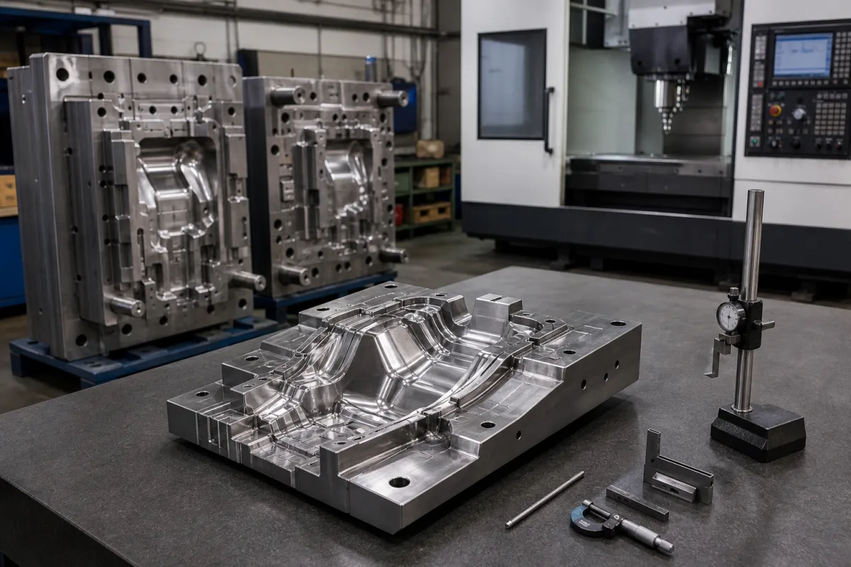
Precision Casting Mold Cavity Insert in a manufacturing environment
Representative product image. Confirm appearance and specifications with the manufacturer.

Product Specifications

Technical details and manufacturing context for Precision Casting Mold Cavity Insert

Definition
A precision-engineered insert that fits into the main mold body to create the internal cavities and features of cast metal components. These inserts are critical for achieving complex geometries, fine surface finishes, and dimensional accuracy in investment casting, die casting, and sand casting processes. They allow for easier mold maintenance, replacement of worn sections, and production of parts with intricate internal details that would be difficult to machine directly into the main mold block. Their modular design reduces overall mold costs and extends tooling life. The insert is precisely machined to the negative shape of the desired cast part feature and secured within the mold assembly. During casting, molten metal flows around the insert, solidifying to form the corresponding positive feature in the final component. After casting, the mold opens and the insert remains with the mold for reuse in subsequent cycles. Typical materials include tool steel (H13), carbide, and copper alloy. Key parameters include insert length (50–300 mm), width (30–200 mm), height (20–150 mm), draft angle (0.5–3 degrees), hardness (45–52 HRC), operating temperature (200–600 °C), surface roughness (0.4–1.6 μm Ra), tolerance grade (IT6–IT8 per ISO 286), material grade (H13 per ASTM A681), and weight (5–50 kg). These values are reference ranges and must be confirmed for the specific model and application. Always verify with the legal manufacturer or supplier.
Working Principle
The insert is precisely machined to the negative shape of the desired cast part feature and secured within the mold assembly. During casting, molten metal flows around the insert, solidifying to form the corresponding positive feature in the final component. After casting, the mold opens and the insert remains with the mold for reuse in subsequent cycles. The insert's geometry, surface finish, and material properties directly influence the cast part's dimensional accuracy and surface quality. Proper draft angles facilitate part ejection, and hardness ensures wear resistance. Operating temperature limits must be respected to avoid thermal fatigue. Regular inspection for wear, cracking, or deformation is necessary to maintain quality. When wear exceeds acceptable limits, the insert can be replaced without discarding the entire mold, reducing downtime and tooling costs.
Common Materials
Tool Steel (H13), Carbide, Copper Alloy
Technical Parameters
ParameterTypical rangeNotes & selection driver
Insert LengthRequired50–300 mmOverall length of the insert component
Insert WidthRequired30–200 mmOverall width of the insert component
Insert HeightRequired20–150 mmOverall height/thickness of the insert
Draft AngleRequired0.5–3 degreesTaper angle for part ejection from mold
Hardness45–52 HRCMaterial hardness for wear resistance
Operating Temperature200–600 °CMaximum continuous operating temperature
Surface Roughness0.4–1.6 μm RaSmoother finish improves part surface quality but increases cost.
Tolerance GradeIT6–IT8Tighter than IT6 is difficult to achieve in casting.ISO 286
Material GradeH13Hot-work tool steel; alternative: 8407 or DIN 1.2344.ASTM A681
Weight5–50 kgHeavier inserts require crane handling; lighter may lack rigidity.

Ranges are indicative industry figures for RFQ preparation, not a supplier commitment. Confirm every value and standard with the legal manufacturer before ordering.

Components / BOM
  • Insert Body Part
    Forms the main shape of the cast feature
    Material: Tool Steel or Carbide
  • Mounting Flange Part
    Secures insert to main mold plate
    Material: Same as body
  • Cooling Channel Optional Part
    Internal passage for temperature control
    Material: Machined cavity

Industry Taxonomies & Aliases

Commonly used trade names and technical identifiers for Precision Casting Mold Cavity Insert.

Industrial Ecosystem & Supply Chain Structure

Complementary Systems
Downstream Applications
Specialized Tooling

Application Fit & Sizing Matrix

Operational Limits
pressure: Up to 100 MPa (14,500 psi) injection pressure
other spec: Slurry concentration: 30-70% solids by weight, Flow rate: 0.5-5.0 L/min per cavity
temperature: Ambient to 1200°C (2192°F) continuous, 1400°C (2552°F) peak
Media Compatibility
✓ Molten aluminum alloys (e.g., A356, 380) ✓ Investment casting wax patterns ✓ Ceramic slurry (alumina-silica based)
Unsuitable: Molten magnesium alloys (due to high reactivity and thermal shock)
Sizing Data Required
  • Casting part volume and geometry (CAD data)
  • Required surface finish (Ra value in microns)
  • Production cycle time and thermal cycling requirements

Reliability & Engineering Risk Analysis

Failure Mode & Root Cause
Thermal fatigue cracking
Cause: Repeated heating and cooling cycles during casting cause thermal stress, leading to crack initiation and propagation in the mold insert material, often exacerbated by rapid temperature changes or inadequate preheating.
Erosion and wear from molten metal flow
Cause: High-velocity molten metal impingement during injection erodes the cavity surface over time, particularly in gate areas and sharp corners, accelerated by abrasive particles in the alloy or improper gating design.
Maintenance Indicators
  • Visible surface cracks or crazing on the cavity insert, especially around edges or high-stress areas, indicating thermal fatigue failure.
  • Dimensional inaccuracies or surface defects in cast parts, such as flashing, incomplete filling, or poor surface finish, signaling wear or damage to the insert.
Engineering Tips
  • Implement controlled heating and cooling protocols, including proper preheating before use and gradual cooling after casting, to minimize thermal shock and stress on the insert material.
  • Apply protective surface coatings, such as ceramic or refractory metal layers, to enhance wear resistance and reduce direct contact with molten metal, extending the insert's operational life.

Indicative industry ranges for design and RFQ preparation. Confirm the exact figures and applicable standard with the manufacturer before specifying.

Compliance & Manufacturing Standards

Applicable Standards
ISO 8062:2020 (Geometrical product specifications (GPS) - Dimensional and geometrical tolerances for moulded parts) ASTM A781/A781M-21 (Standard Specification for Castings, Steel and Alloy, Common Requirements, for General Industrial Use) DIN EN 10204:2004 (Metallic products - Types of inspection documents)

Quoted from the published standard.

Manufacturing Precision
  • Cavity dimensions: +/-0.05mm
  • Surface finish: Ra 0.8μm
Quality Inspection
  • Coordinate Measuring Machine (CMM) dimensional verification
  • Hardness testing (Rockwell C scale)

Manufacturers of Precision Casting Mold Cavity Insert

2 companies list this product among what they make. Company figures are quoted from each company's own website; every card states where the relationship came from.

Dongguan Mingshang Mould Parts Co., Ltd
Dongguan, Guangdong, CN
Listed on the company's own website · profile compiled by CNFX from public sources
Listed there as: “core inserts”
View source page ↗ minsmold.com · checked 2026-09-04
Jiangsu Veoell Intelligent Equipment Technology Co., Ltd.
Nanjing, Jiangsu, CN
Listed on the company's own website · profile compiled by CNFX from public sources
Listed there as: “1V DIE INSERT”
View source page ↗ veoell.com · checked 2026-09-10

Manufacturer listings support early research and capability understanding. They are not certification, ranking, or transaction guarantees.

Share this page
Technical documentation
Request current drawings, revision history, and a signed specification sheet.
Manufacturing capability
Verify equipment lists, process limits, capacity, and representative production evidence.
Inspection readiness
Confirm test methods, calibrated equipment, sampling plans, and traceable reports.
Supplier transparency
Check the legal entity, factory address, ownership, certifications, and direct contacts.

CNFX does not score or rank suppliers. Buyers must verify all claims and documents with the legal manufacturer before ordering.

Frequently Asked Questions

What materials are available for this insert?

According to the directory, available materials include tool steel (H13), carbide, and copper alloy. The specific material grade for H13 is listed as per ASTM A681, but you should confirm the exact grade and heat treatment with the supplier for your application.

What are the typical dimensional ranges?

Reference ranges are: length 50–300 mm, width 30–200 mm, height 20–150 mm, and weight 5–50 kg. These are general ranges; the actual dimensions depend on the mold design and casting requirements. Always verify with the manufacturer.

What tolerance grade can be achieved?

The directory lists a tolerance grade of IT6–IT8 per ISO 286. Tighter than IT6 is difficult to achieve in casting. However, the actual achievable tolerance depends on the casting process, material, and geometry. Confirm with your supplier.

How should I verify the insert's suitability?

Check the insert's dimensions, material grade, hardness, operating temperature, surface roughness, and tolerance against your casting requirements. Also, ensure the draft angle is appropriate for part ejection. Always consult the legal manufacturer or supplier for model-specific data and compliance.

Data Basis

Editorial classification, named public sources where available, and source-reviewed manufacturer records.

Preliminary Technical Classification
This page supports structured research, RFQ preparation, and supplier evaluation. It does not replace buyer-led supplier qualification, standards review, or technical approval.
Buyer enquiry

Request manufacturing insight for Precision Casting Mold Cavity Insert

Ask for use case, specification boundaries, supplier type, and RFQ preparation information for this product.

Where it goes
Straight to the CNFX editorial desk, and to the manufacturer if this product is linked to a claimed profile. Nothing is broadcast to a supplier list.
Your details stay here
We do not sell or rent enquiry data, and we do not add you to a mailing list. Used only to answer this request.
No commission, no middleman
CNFX is a directory. We take no cut of any order and never negotiate on a supplier's behalf.
What we don't claim
A listing is not an endorsement. Qualify every supplier and verify every figure yourself before ordering.

Your business information is used only to process this request.

Thank you! Your message has been sent. We'll respond within 1–3 business days.
Sorry, we couldn't send your message. Please try again, or email us at [email protected].

Need to Manufacture Precision Casting Mold Cavity Insert?

Compare manufacturer profiles with relevant product and process capability.

Previous Product
Vacuum Induction Degassing Unit
Last Product
Get QuotesChat