Editorial Technical Reference

Precision Casting Mold Core Insert

This page explains how Precision Casting Mold Core Insert is classified within Foundries. Technical values and manufacturer relationships are research references; confirm the current specification and supplier evidence for each order.

Technical Definition & Core Assembly

A precision-engineered removable insert used in foundry molds to create complex internal geometries in metal castings.

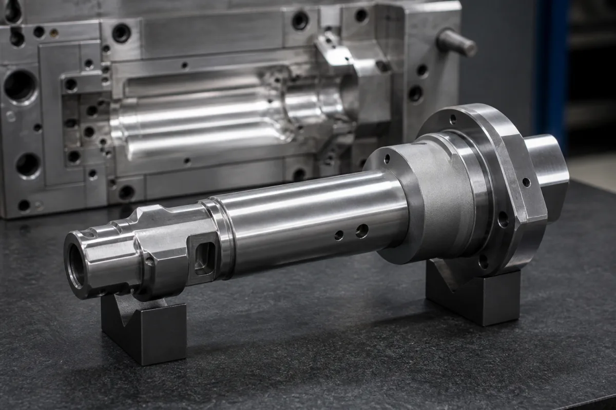
Representative product image. Confirm appearance and specifications with the manufacturer.

Product Specifications

Technical details and manufacturing context for Precision Casting Mold Core Insert

Definition
A precision-engineered removable insert used in foundry molds to create complex internal geometries in metal castings. This component enables the production of hollow or intricate internal features that cannot be formed by the main mold body. It is critical for manufacturing components with internal passages, cooling channels, or complex internal structures in automotive, aerospace, and industrial equipment applications. The insert allows for efficient mold assembly and disassembly while maintaining dimensional accuracy across production runs. The insert is typically made from materials such as H13 tool steel, copper alloy, or graphite, selected based on thermal conductivity, hardness, and operating temperature requirements. Key parameters include insert length (50–300 mm), diameter (10–80 mm), draft angle (0.5–3 degrees), thermal conductivity (15–50 W/m·K), hardness (45–55 HRC per ASTM E18), operating temperature (-40 to 300 °C), surface roughness (Ra 0.4–0.8 μm per ISO 1302), tensile strength (800–1200 MPa per ASTM E8), density (7.8–8.1 g/cm³ for steel grades), weight (0.5–5 kg per insert), and corrosion resistance (ISO 9227 salt spray test rating). These values are reference ranges and must be verified for the specific model and application. The insert is positioned within the mold cavity before pouring, and after solidification, it is removed through designated access points, leaving accurately formed internal features. Proper selection requires consideration of casting material, geometry complexity, production volume, and thermal management. Verification questions include confirming material grade, dimensional tolerances, and compliance with relevant standards. Maintenance signals include wear, deformation, or surface degradation, which may affect casting quality. Failure boundaries include cracking, erosion, or loss of dimensional accuracy, necessitating replacement. Always consult the legal manufacturer or supplier to confirm model-specific values and standards.
Working Principle
The insert is precisely positioned within the mold cavity before pouring molten metal. After solidification, the insert is removed through designated access points, leaving behind accurately formed internal features in the casting. The insert's geometry and surface finish directly influence the final casting's internal dimensions and quality. Proper draft angles facilitate removal, and thermal conductivity affects cooling rates. The insert must withstand repeated thermal cycles and mechanical stresses without deformation. Its design must allow for efficient assembly and disassembly while maintaining alignment and dimensional stability. The removal process is critical to avoid damaging the casting or the insert itself. The insert's material and surface treatment are chosen to balance wear resistance, thermal performance, and cost. Regular inspection and maintenance are necessary to ensure consistent performance. The insert's operating limits, such as maximum temperature and mechanical load, must be respected to prevent premature failure. The insert is a replaceable component, and its lifespan depends on usage conditions and maintenance practices.
Common Materials
H13 Tool Steel, Copper Alloy, Graphite
Technical Parameters
ParameterTypical rangeNotes & selection driver
Insert LengthRequired50–300 mmOverall length of the insert component
Insert DiameterRequired10–80 mmMaximum outer diameter of cylindrical sections
Draft AngleRequired0.5–3 degreesTaper angle for mold release
Thermal ConductivityRequired15–50 W/m·KHeat transfer capability of insert material
HardnessRequired45–55 HRCMaterial hardness for wear resistanceASTM E18
Operating Temperature-40–300 °CMaximum continuous operating temperature
Surface RoughnessRa 0.4–0.8 μmCritical for casting finishISO 1302
Tensile Strength800–1200 MPaDepends on alloyASTM E8
Density7.8–8.1 g/cm³For steel grades
Weight0.5–5 kgPer insert
Corrosion ResistanceISO 9227 hSalt spray test ratingISO 9227

Ranges are indicative industry figures for RFQ preparation, not a supplier commitment. Confirm every value and standard with the legal manufacturer before ordering.

Components / BOM
  • Insert Body Part
    Forms the primary internal casting geometry
    Material: H13 Tool Steel
  • Cooling Channel Optional Part
    Regulates temperature during casting process
    Material: Copper Alloy
  • Extraction Thread Part
    Provides attachment point for removal tools
    Material: Tool Steel

Industry Taxonomies & Aliases

Commonly used trade names and technical identifiers for Precision Casting Mold Core Insert.

Industrial Ecosystem & Supply Chain Structure

Complementary Systems
Downstream Applications
Specialized Tooling

Application Fit & Sizing Matrix

Operational Limits
pressure: Max 150 MPa (21,750 psi) during injection/casting, typical operating 50-100 MPa
flow rate: Dependent on slurry viscosity and cavity geometry, typically 0.5-5.0 m/s for molten metal flow
temperature: Up to 1600°C (2912°F) for short-term exposure, continuous use recommended below 1400°C (2552°F)
slurry concentration: 60-75% solids by weight for ceramic slurries, viscosity range 500-5000 cP
Media Compatibility
✓ Aluminum alloys (A356, A380) ✓ Stainless steel (316L, 17-4PH) ✓ Nickel-based superalloys (Inconel 718, Hastelloy X)
Unsuitable: Highly corrosive molten metals (e.g., titanium alloys without protective coatings) due to chemical attack and thermal stress
Sizing Data Required
  • Cavity volume and geometry (including draft angles and undercuts)
  • Required surface finish (Ra value) and dimensional tolerance (± mm)
  • Expected production cycle count and thermal cycling conditions

Reliability & Engineering Risk Analysis

Failure Mode & Root Cause
Thermal fatigue cracking
Cause: Repeated heating and cooling cycles during casting cause thermal expansion and contraction stresses, leading to crack initiation and propagation in the mold core insert material.
Erosion and washout
Cause: High-velocity molten metal flow during injection causes abrasive wear and material removal, particularly in thin sections and sharp edges of the core insert.
Maintenance Indicators
  • Visible cracks or crazing on the insert surface visible during routine inspection
  • Dimensional deviations in cast parts indicating insert wear or deformation
Engineering Tips
  • Implement controlled preheating and cooling protocols to minimize thermal shock and maintain consistent operating temperatures
  • Apply specialized ceramic or refractory coatings to critical wear surfaces to enhance erosion resistance and reduce metal adhesion

Indicative industry ranges for design and RFQ preparation. Confirm the exact figures and applicable standard with the manufacturer before specifying.

Compliance & Manufacturing Standards

Applicable Standards
ISO 8062:2020 (Geometrical product specifications (GPS) - Dimensional and geometrical tolerances for moulded parts) ASTM A703/A703M-22 (Standard Specification for Steel Castings, General Requirements, for Pressure-Containing Parts) DIN EN 10213:2007 (Steel castings for pressure purposes)

Quoted from the published standard.

Manufacturing Precision
  • Dimensional tolerance: +/-0.1mm per 25mm (for critical features)
  • Surface roughness: Ra 0.8μm maximum (for mold contact surfaces)
Quality Inspection
  • Coordinate Measuring Machine (CMM) dimensional verification
  • Liquid Penetrant Inspection (LPI) for surface defect detection

Manufacturers of Precision Casting Mold Core Insert

Manufacturer profiles associated with Precision Casting Mold Core Insert.

Sourcing Precision Casting Mold Core Insert from China?
Tell us your specification and target quantity — we will match it against manufacturer records and come back with the factories that fit.
Request manufacturers We manufacture this

Manufacturer listings support early research and capability understanding. They are not certification, ranking, or transaction guarantees.

Technical documentation
Request current drawings, revision history, and a signed specification sheet.
Manufacturing capability
Verify equipment lists, process limits, capacity, and representative production evidence.
Inspection readiness
Confirm test methods, calibrated equipment, sampling plans, and traceable reports.
Supplier transparency
Check the legal entity, factory address, ownership, certifications, and direct contacts.

CNFX does not score or rank suppliers. Buyers must verify all claims and documents with the legal manufacturer before ordering.

Frequently Asked Questions

What materials are available for this insert?

According to the directory, the insert can be made from H13 tool steel, copper alloy, or graphite. The choice depends on thermal conductivity, hardness, and operating temperature requirements. Confirm the exact material grade with the supplier.

What are the typical dimensions and tolerances?

Reference ranges include length 50–300 mm, diameter 10–80 mm, and draft angle 0.5–3 degrees. Surface roughness is Ra 0.4–0.8 μm per ISO 1302. These are directory ranges; actual values must be verified for your specific application.

How is the insert removed after casting?

The insert is removed through designated access points after the metal solidifies. The design includes draft angles and access features to facilitate removal without damaging the casting. The exact removal method depends on the mold design and insert geometry.

What standards apply to this component?

Standards referenced include ASTM E18 for hardness, ISO 1302 for surface roughness, ASTM E8 for tensile strength, and ISO 9227 for corrosion resistance. These are verification references; compliance must be confirmed with the manufacturer.

Data Basis

Editorial classification, named public sources where available, and source-reviewed manufacturer records.

Preliminary Technical Classification
This page supports structured research, RFQ preparation, and supplier evaluation. It does not replace buyer-led supplier qualification, standards review, or technical approval.
Buyer enquiry

Request manufacturing insight for Precision Casting Mold Core Insert

Ask for use case, specification boundaries, supplier type, and RFQ preparation information for this product.

Where it goes
Straight to the CNFX editorial desk, and to the manufacturer if this product is linked to a claimed profile. Nothing is broadcast to a supplier list.
Your details stay here
We do not sell or rent enquiry data, and we do not add you to a mailing list. Used only to answer this request.
No commission, no middleman
CNFX is a directory. We take no cut of any order and never negotiate on a supplier's behalf.
What we don't claim
A listing is not an endorsement. Qualify every supplier and verify every figure yourself before ordering.

Your business information is used only to process this request.

Thank you! Your message has been sent. We'll respond within 1–3 business days.
Sorry, we couldn't send your message. Please try again, or email us at contact@cnfx.com.

Need to Manufacture Precision Casting Mold Core Insert?

Compare manufacturer profiles with relevant product and process capability.

Previous Product
Vacuum Induction Degassing Unit
Last Product
Get QuotesChat