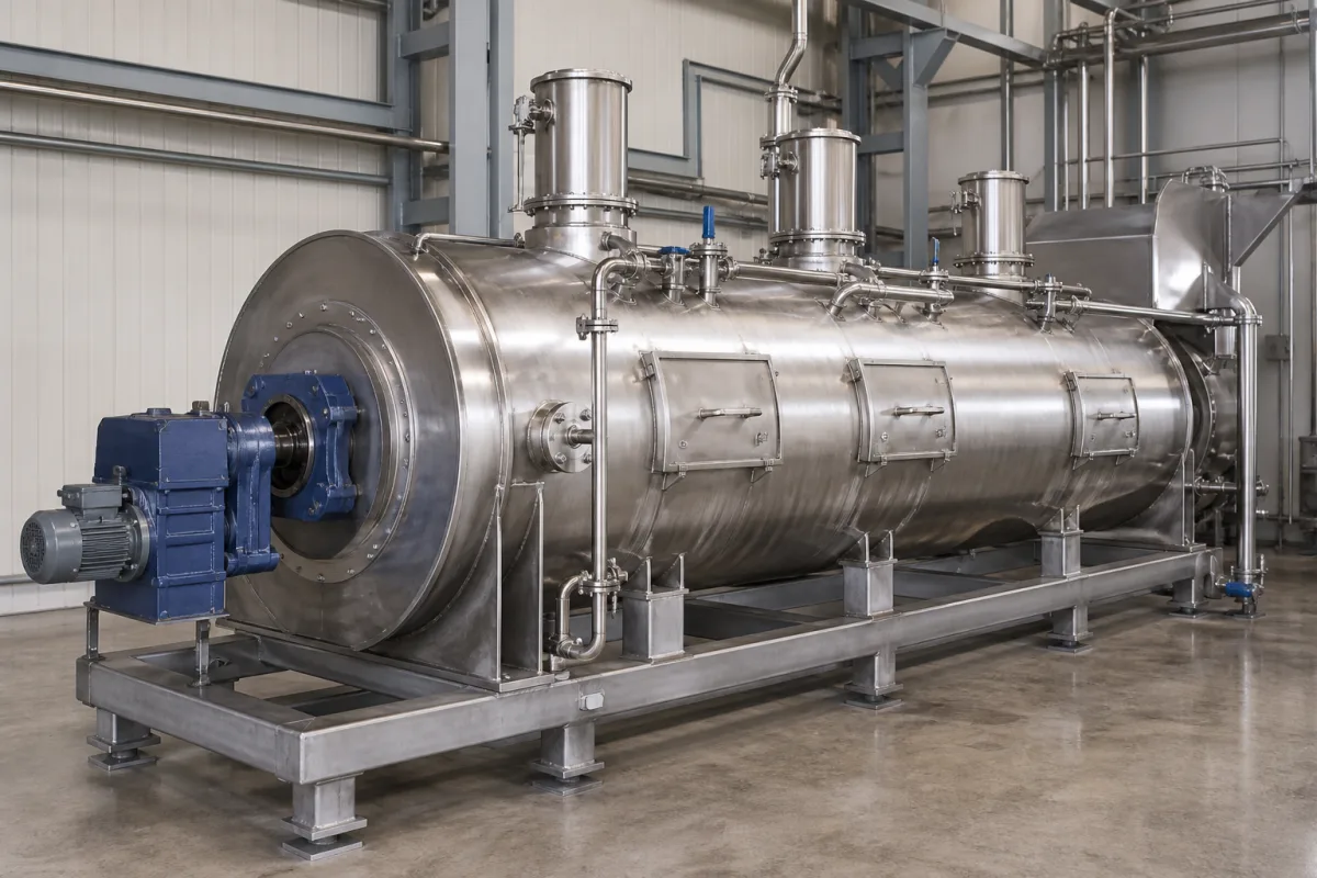
Feed conditioning and retention chamber: sizing steam conditioning time, temperature and moisture for a validated Salmonella kill step before pelleting
The steam conditioner and retention chamber ahead of a feed pellet mill as a Salmonella kill step · D-values of 178.2 s at 65 °C and 3.1 s at 85 °C in 12 % moisture broiler mash, 30-second conditioners for 12 to 30 t/h, and why lab-derived retention times did not always give 5 logs at pilot scale
In a pelleting line the heat that kills Salmonella is applied before the die: superheated steam is mixed into the mash in a conditioner and, where fitted, held at temperature in a retentioner. Bühler's food and feed safety team describes the die's own heating as negligible for microbial kill because the feed is in the die so briefly. Temperature, moisture and retention time in the chamber ahead of it set the kill.
Steam conditioners and retention (retentioner, hygieniser) chambers ahead of feed pellet mills, judged as a thermal kill step: retention time and how it is set, product temperature, moisture after steam addition, chamber volume and fill, and how the kill is validated. The pellet mill itself, its die, rolls, capacity, die speed and pellet durability, is covered on the High-capacity pellet mill for animal feed page. Extruder preconditioners, expanders and coolers are not covered here.
CNFX editorial research · Sources checked October 13, 2026 · 4 sources
How fast Salmonella dies in conditioned mash: D-values from 178.2 s at 65 °C to 0.7 s at 85 °C, and the moisture that changes them
Steghöfer, Limburn and Margas screened five feed-associated Salmonella strains, chose S. Agona strain RA1052, isolated from animal feed, for its heat resistance, and measured its D-values (time for a 1-log, 90 % reduction) in broiler mash in a customised autoclave. [1]
Editorial calculation: 5-log time = 5 × D; z = 20 °C / log₁₀(D65 / D85), for example 20 / log₁₀(178.2 / 3.1) ≈ 11.4 °C. These are laboratory values in one matrix; the authors selected Enterococcus faecium ATCC 8459 (NRRL B-2354), of equivalent heat resistance, as the surrogate for on-site challenge tests. [1]
Bühler's Edyta Margas sets out the operating window that matters: conditioning and retentioning run at 60–90 °C, 30–240 seconds retention and 12–19 % moisture (water activity about 0.7–0.9), and inactivation rises with each of temperature, moisture and time. Low moisture raises Salmonella's heat resistance, so dry raw materials need higher temperature, longer retention or added water. She cites earlier studies proposing 87 °C at 15 % moisture for a 5-log reduction in meat and bone meal, with no retention time given, and 93 °C for 90 seconds at 15 % moisture for a 4-log reduction in turkey grower feed. [2]
State the target organism and log reduction, the lowest mash moisture you process, and the temperature the chamber must hold; ask for the validation data behind any claimed kill.
02
Retention time from chamber volume, fill and throughput: about 35 s in a 750 L conditioner at 30 t/h
CPM states that its design raises the conditioner's filling degree to up to 70 %, and that retention is adjusted by varying the variable-speed mixer shaft remotely; the conditioners use adjustable T-shaped paddles and picks and an internal steam manifold, and can blend up to 8 % molasses. [4]
Editorial calculation: retention ≈ chamber volume × fill × bulk density ÷ throughput. With an assumed mash bulk density of 0.55 t/m³, the 24LT10 at 70 % fill holds 0.75 × 0.70 × 0.55 ≈ 0.29 t, which at 30 t/h is about 35 s; the two smaller models give about 34–35 s at their rated capacities, close to the 30 s rating. [4] Against the D-values above, 30–35 s exceeds the laboratory 5-log time at 85 °C (15.5 s at 12 % moisture) but is far short of the 14.9 min needed at 65 °C, which is why a separate retentioner is used to hold product at temperature for longer. [1][2]
Give the throughput range, the retention time required at the lowest and highest throughput, and the bulk density of your mash; ask how fill level is held constant when throughput changes.
03
Proving the kill at scale: lab-derived retention times that fell short of 5 logs in a pilot retentioner
Bühler then ran its pilot conditioning and retentioning system, with heating mats on the retentioner to prevent heat loss and extra temperature sensors, at 75, 80 and 85 °C and 12 % moisture, using mash inoculated with about 10⁸ cfu/g of the Enterococcus faecium surrogate. Retention times were calculated from the laboratory D-values, and throughput was varied between 1 and 5 t/h to keep the retentioner fill constant. Not all settings reached the expected 5-log reduction. [3]
Margas's conclusion is that laboratory trials give only indications, because they miss process fluctuations and product inhomogeneity, and that a trusted kill step at industrial scale needs stable process conditions with sensors at defined key locations monitoring the critical parameters continuously. [3] Feed components such as fat, minerals and protein also change inactivation, so parameters cannot be transferred unchanged between recipes. [2]
Ask where temperature is measured in the conditioner and retentioner, whether the retentioner is insulated or heated, and whether a surrogate challenge test at your recipe and throughput is offered.
04
What to send when specifying a feed conditioning and retention chamber
Paste it into your enquiry below or into an email to a maker, then replace every bracket.
Feed: [species; recipe type; fat; bulk density; moisture before and after steam]
Throughput: [t/h range]
Kill step: [target organism; log reduction; temperature; retention time]
Chamber: [conditioner volume; retentioner volume; fill control; shaft speed range]
Steam and liquids: [steam pressure and quality; molasses or fat addition]
Monitoring: [temperature sensor locations; recording; insulation or heating]
Validation: [surrogate challenge test; acceptance criteria]
Explore company information and manufacturing capabilities, then discuss the scope of your project with a relevant supplier.
Share this page
Compiled and source-reviewed by the CNFX editorial team.
Each manufacturer above links to the page on that company's own website where the product is listed, with the date we checked it. How we source and review
· Page last updated 13 October 2026
Buyer questions
How long must feed be held at temperature to kill Salmonella?
In one laboratory study in broiler mash at 12 % moisture, the D-value of S. Agona was 178.2 s at 65 °C and 3.1 s at 85 °C, so a 5-log reduction takes about 14.9 min or 15.5 s (editorial calculation); pilot-scale results can fall short of lab predictions. [1][3]
Why does mash moisture matter in conditioning?
Salmonella's heat resistance rises at low moisture; at 19 % moisture the D-values were 81.1 s at 65 °C and 0.7 s at 85 °C, against 178.2 s and 3.1 s at 12 %. [1][2]
What retention time does a standard feed conditioner give?
CPM rates its 300, 390 and 750 L conditioners at 30 seconds for 12, 16 and 30 t/h, adjustable through mixer shaft speed. [4]
Does the pellet die add to the Salmonella kill?
Bühler's Edyta Margas describes the extra heating in the die as negligible because the residence time there is short; the main effect is in conditioning and retentioning. [2]
Sources and what still needs a direct check
Sources checked 2026-10-13. Inactivation kinetics come from a 2021 Journal of Applied Poultry Research study; the process window and pilot validation from Bühler's food and feed safety leader writing in Feed Planet Magazine; conditioner volumes, capacities and retention ratings from CPM.