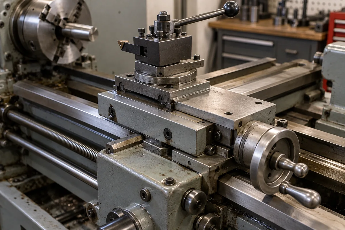
Lathe cross slide: the dovetail slide, gib, feed screw and graduated dial that set depth of cut on a manual centre lathe
Manual centre lathes · dial graduation and how it reads against diameter, taper gib and backlash adjustment, power cross feed, and facing squareness
On a manual centre lathe the cross slide is the short slide that runs across the carriage at right angles to the spindle, carrying the compound rest and the tool post. Every facing cut and every depth of cut in turning is set on its handwheel dial, so the way that dial is graduated, the play in its screw and the fit of its gib decide whether a part comes out at the size dialled. This page reads those details from two lathe manuals and a classic test method.
Cross slides of manual centre (engine) lathes together with the compound rest (top slide) they carry: dovetail ways and taper gibs, the cross-feed screw and nut and their backlash, graduated dials and how they read against diameter, power cross feed, and the squareness of cross-slide travel to the spindle. Ball-screw single-axis stages for automation and optics are covered on the Linear positioning stage (ball screw driven) page and profile-rail and polymer slide guidance on the Linear motion system page. CNC lathes and their servo X axis are covered on the Universal CNC lathe and Economic CNC lathe pages. Cutter drives for bulk samplers have their own page. Cross-slide drill-press vises and milling-machine XY tables are outside this page.
CNFX editorial research · Sources checked October 12, 2026 · 3 sources
Dial graduation, travel per turn and whether the dial reads radius or diameter
Feeding a turning tool in by 0.001 in takes 0.002 in off the diameter of the work, as J. Latta put it in Model Engineer, so the first question about any cross-slide dial is whether its numbers mean tool movement or diameter. [3]
The two manuals describe their dials differently. Grizzly's G0709 manual gives the example that turning its handwheel 0.015 in on the dial removes 0.030 in from the diameter, which matches Latta's rule, yet the same paragraph says a full revolution of 0.100 in equals 0.200 in of cross-slide movement. [1][3] Editorial note: with a 10 TPI screw one turn moves the slide 0.100 in, so the second statement reads as diameter, not slide travel; check on the machine with an indicator before trusting either description.
Grizzly's G0602 compound rest has the same 0.001 in graduations but 0.04 in (1.02 mm) per turn, and is also indirect-read. [2] Editorial calculation: the G0602's 0.06 in per turn in 0.001 in steps puts 60 divisions on the dial, and its 6-1/2 in of travel takes about 108 turns; the G0709's 0.100 in per turn gives 100 divisions and about 67 turns for its 6-11/16 in (about 170 mm). [2][1]
10 TPI leadscrew, 0.001 in increments; called a Standard Dial with a 1:2 ratio [1]
When ordering a lathe or a replacement cross slide, ask for the screw pitch, the dial graduation and travel per turn, and whether the dial reads tool movement or diameter, in inch or metric.
02
Taper gib in the dovetail ways, gib lock and cross-feed nut backlash
On Grizzly's G0709 the cross slide and compound slide each run in dovetailed ways with a long steel wedge, the gib, between slide and way; two opposing gib screws, one at each end, move and hold it, so that shifting the gib widens or narrows the gap and with it the slide's rigidity. [1]
The manual gives two settings at the ends of the range: for heavy turning and facing, tighten the gibs for rigidity and loosen the leadscrew nuts for shock protection; for high-tolerance, light work, loosen the gibs so the slide moves in small steps without binding or tool leap, and tighten the leadscrew nuts for fine handwheel control. Adjustment is in 1/8-turn steps of the gib screws, and a separate gib lock screw holds the slide rigid without retightening the gib. [1]
Backlash, the free play felt when the handwheel changes direction, is read on the dial collar. [1] On the G0709 it is taken up by a cap screw on the cross-slide leadscrew nut, tightened in small steps and tested after each. [1] Grizzly's G0602 manual warns that reducing backlash below 0.002 in is impractical and wears the leadscrew faster. [2] Editorial calculation: 0.002 in is two divisions on a 0.001 in dial, so approach every dialled cut from the same direction rather than trying to tighten the play out.
03
Power cross feed against longitudinal feed
Grizzly lists 32 cross feeds of 0.00046 to 0.03231 in/rev on the G0709, against 24 longitudinal feeds of 0.00168 to 0.1175 in/rev; the apron's feed selection lever engages either one, and a lockout stops it and the half nut being engaged together. [1]
Editorial calculation: 0.00046 ÷ 0.00168 ≈ 0.27 and 0.03231 ÷ 0.1175 ≈ 0.27, so on this lathe each cross feed is about 0.27 of the matching longitudinal feed; a facing feed has to be read from the cross-feed column, not the turning one. [1] The smaller G0602 lists 9 longitudinal feeds of 0.0025 to 0.0140 in/rev and no separate cross-feed range in the specifications reviewed. [2]
04
Checking that the cross slide faces flat or slightly hollow
Latta's test for squareness of the cross slide to the spindle uses a faceplate and a test indicator on the tool post: read the indicator against a marked spot on the faceplate at one end of cross-slide travel, then wind the slide across, turn the faceplate half a turn and read the same spot again. Equal readings mean the slide is at right angles to the spindle, and the test does not depend on the faceplate running true. [3]
Latta recommends adjusting the lathe to face slightly hollow rather than convex, by not more than a thousandth of an inch over the full travel of the slide, and advises repeating the test with the saddle locked to see whether the lock twists the saddle. [3] Editorial calculation: on the G0709's 6-11/16 in of cross-slide travel, 0.001 in is about 0.00015 in per inch. [3][1]
05
Send the lathe model, the screw and dial, and the travel
Paste it into your enquiry below or into an email to a maker, then replace every bracket.
Lathe: [make; model; swing over bed and over cross slide]
Cross slide: [travel; dovetail width; gib type; new slide or replacement]
Screw and dial: [pitch or TPI; travel per turn; graduation; reads tool movement or diameter; inch or metric]
Compound rest: [travel; graduation; angle scale]
Feeds: [power cross feed range]
Checks: [backlash; facing squareness over full travel]
Explore company information and manufacturing capabilities, then discuss the scope of your project with a relevant supplier.
Share this page
Compiled and source-reviewed by the CNFX editorial team.
Each manufacturer above links to the page on that company's own website where the product is listed, with the date we checked it. How we source and review
· Page last updated 13 October 2026
Buyer questions
Does a cross-slide dial show depth of cut or diameter?
It depends on the lathe. Feeding the tool 0.001 in takes 0.002 in off the diameter; Grizzly's G0602 dial shows the tool movement, and its G0709 manual gives a 0.015 in dial move removing 0.030 in from the diameter. [3][2][1]
What does the gib on a cross slide do?
On Grizzly's G0709 it is a long steel wedge in the dovetail ways; moving it with opposing screws sets how rigid or free the slide is. [1]
How much backlash should a cross slide have?
Grizzly's G0602 manual says reducing it below 0.002 in is impractical and wears the leadscrew. [2]
Should a lathe face flat?
Latta recommended slightly hollow rather than convex, by no more than 0.001 in over the full cross-slide travel. [3]
Sources and what still needs a direct check
Sources checked 2026-10-12. Two Grizzly owner's manuals give the cross-slide data for those two lathes; J. Latta's 1955 Model Engineer article, hosted by GadgetBuilder, describes a workshop test method, not a standard.