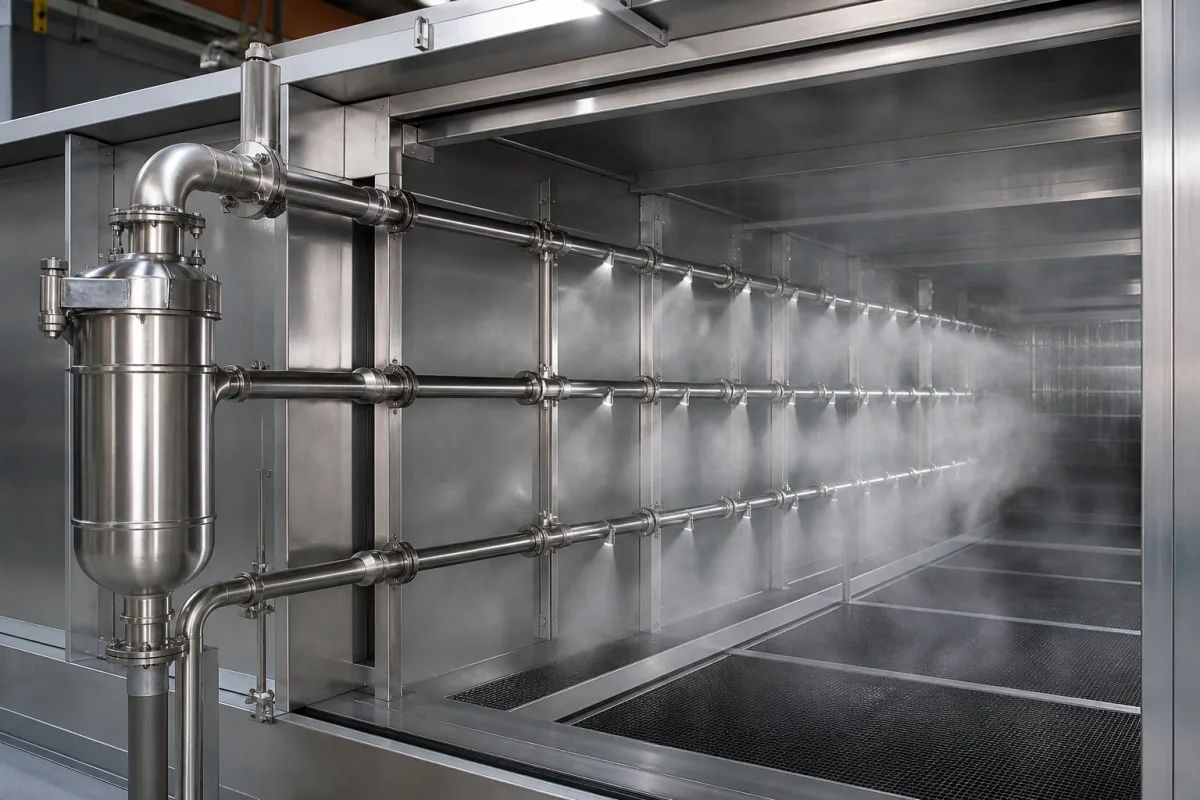
Steam dispersion manifold and multi-tube header panel for duct humidification
Humidifier steam dispersion headers · tube spacing versus non-wetting distance, hot-tube heat gain and condensate, manifold pressure
A steam dispersion manifold, or multi-tube header panel, is the assembly of a supply header, vertical or horizontal dispersion tubes with nozzles or orifices, and a condensate drain that releases humidifier steam into an air duct or air handling unit. It is the downstream part of a steam humidification system, bought on its own when a steam source already exists or when the dispersion has to fit a short duct. Ask three things first: how much straight duct is available after the panel, how far apart the tubes are, and whether the tubes are insulated against heat gain.
Steam dispersion assemblies placed in ducts and air handling units: single dispersion tubes, steam-jacketed tubes, multi-tube header panels and their separators, nozzles and drains, specified by tube spacing, available non-wetting distance, steam pressure, tube heat gain and materials. Complete humidifiers with their steam generators, water treatment and controls are covered on the Humidification system for air handling units and industrial spaces page. Adiabatic spray and atomising nozzles, process spray headers and steam piping outside the air stream are outside this page.
CNFX editorial research · Sources checked October 12, 2026 · 4 sources
Fit tube spacing to the non-wetting distance you have
RL Deppmann defines absorption distance as the length of duct needed to turn visible water vapour into invisible gas, and lists three factors: duct or AHU air temperature, the difference between entering and leaving RH, and how well steam and air are mixed. It states that a single steam-jacketed dispersion tube with a single row of dispersion holes requires an absorption distance of at least 3 ft, and points AHU installations, where the distance for air and steam mixing is short, to multiple tubes with equally spaced dispersion holes. [1] Editorial calculation: 3 ft = 0.91 m.
Eric Landry's 2014 master's thesis at the École de technologie supérieure, carried out with the humidifier maker Neptronic, measured the non-wetting distance, the distance downstream of the dispersion assembly beyond which an obstacle in the air stream cannot get wet. Its test duct was 61 cm wide by 51 cm high, with vertical dispersion tubes of 3.5 cm outside diameter and 0.9 mm wall. Five panels were compared: 7 tubes at 7.6 cm (3 in) centres, 4 at 15.2 cm, 3 at 20.3 cm, 2 at 30.5 cm and 1 tube in the 61 cm duct. [2]
The results show that increasing the spacing between tubes increases the non-wetting distance, and that for a fixed humidity rise the upstream humidity also changes it. The tests ran at 12.8 °C (55 °F) air and 2.54 m/s (500 fpm), with upstream RH of 10–60% and downstream RH below 85%, and the thesis states that its prediction model is valid only for those conditions. [2]
Editorial note: read a supplier's non-wetting or absorption distance as a figure for stated air temperature, velocity and RH rise. Give the supplier the straight length available after the panel and the first obstruction (coil, filter, fan, damper or elbow), and ask for the predicted distance at your conditions.
Send the duct or AHU section size, air flow and velocity, entering air temperature and RH, target leaving RH, steam load in kg/h, steam source and pressure, straight length available downstream and the first obstruction, and whether the tubes must be insulated.
02
Limit heat gain and condensate from hot tubes
DriSteem's patent US 10,088,180 B2 notes that dispersion tubes can reach around 212 °F on the outer surface and that, when a large number of tubes get hot, they heat the surrounding duct air and reduce the effect of the cooling and humidification process. It also explains that the number of tubes and their spacing are based on the needed non-wetting or absorption distance. [3] Editorial calculation: 212 °F = 100 °C.
An earlier DriSteem patent, US 7,744,068 B2, covers insulation on dispersion tubes that meets 25/50 flame/smoke indexes for UL 723/ASTM E-84 with thermal conductivity below about 0.35 W/m·K. It reports that a PVDF insulation reduced the outer surface temperature of the tubes from 212 °F to around 95 °F at 500 fpm and 55 °F air, cut total system condensate by about 45–60% and the condensate from the tubes themselves by around 65–70%. Examples in the patent pair a 1/8-inch layer of insulation with tubes of 1-1/2 and 2 inches in diameter. [4] Editorial calculation: 95 °F ≈ 35 °C; 1/8 in ≈ 3.2 mm; 1-1/2 in ≈ 38 mm and 2 in ≈ 51 mm.
US 10,088,180 B2 also describes the steam feeding the manifolds: from a boiler or electric or gas humidifier at low pressure (for example less than 1 psi), or at higher pressures such as about 2 psi to 60 psi, with the steam inside the manifold at about atmospheric pressure where it meets the duct air. [3] Editorial calculation: 60 psi ≈ 0.41 MPa; 1 psi ≈ 6.9 kPa. Ask which steam pressure range the panel, its separator and its nozzles are built for.
03
Compare dispersion assembly types
The sources reviewed describe these arrangements; each changes the downstream length the duct must provide.
Type
What the sources say
Ask the supplier for
Single dispersion tube
At least 3 ft absorption distance for one steam-jacketed tube with one row of holes. [1]
Predicted distance at your air conditions.
Multi-tube header panel
Tube spacing from 7.6 cm to 61 cm tested; wider spacing gave longer non-wetting distance. [2]
Tube count, spacing and nozzle pitch.
Insulated multi-tube panel
PVDF insulation reduced tube surface from 212 °F to about 95 °F. [4]
Insulation material, thickness, fire rating.
Low-pressure manifold
Fed by a humidifier at less than 1 psi in one example. [3]
Steam enters through the header, leaves through the tube nozzles and returns as condensate through the drain; each part below is a separate order line.
Component
Role
Fix in the order
Supply header / manifold
Carries steam to the tubes; near atmospheric pressure at the outlet. [3]
Size, material, connection.
Dispersion tubes
Spread steam across the section; spacing sets the non-wetting distance. [2]
Count, diameter, spacing, length.
Nozzles or orifices
Release steam; perforated tubes may distribute it more evenly. [3]
Pitch, orifice size, orientation.
Steam jacket (option)
Keeps the tube hot; a single jacketed tube needs at least 3 ft. [1]
1 company lists this product among what they make. Company figures are quoted from each
company's own website; every card states where the relationship came from.
Explore company information and manufacturing capabilities, then discuss the scope of your project with a relevant supplier.
Share this page
Compiled and source-reviewed by the CNFX editorial team.
Each manufacturer above links to the page on that company's own website where the product is listed, with the date we checked it. How we source and review
· Page last updated 13 October 2026
Buyer questions
How much duct length does a single steam dispersion tube need?
RL Deppmann states that a single steam-jacketed tube with one row of dispersion holes needs an absorption distance of at least 3 ft. [1]
Does tube spacing affect the non-wetting distance?
Yes. The ETS study found that increasing the spacing between vertical dispersion tubes increased the non-wetting distance, tested from 7.6 cm to 61 cm spacing. [2]
Why insulate steam dispersion tubes?
A DriSteem patent reports PVDF insulation lowered tube surface temperature from 212 °F to around 95 °F and cut total system condensate by about 45–60%. [4]
Sources and what still needs a direct check
Sources checked 2026-10-12. RL Deppmann is an HVAC equipment representative explaining absorption distance; the École de technologie supérieure thesis is an experimental study made with a humidifier maker; the two DriSteem patents describe dispersion tube design and insulation test results as stated by the applicant.