Editorial Technical Reference

End Effector Mount

This page explains how End Effector Mount is classified within Machinery and Equipment Manufacturing. Technical values and manufacturer relationships are research references; confirm the current specification and supplier evidence for each order.

Technical Definition & Core Assembly

Interface component connecting an industrial robot arm to various end effectors

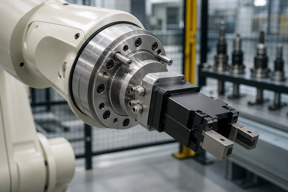
Representative manufacturing scene; not a photograph of a specific supplier or model.

Product Specifications

Technical details and manufacturing context for End Effector Mount

Definition
A mechanical interface that attaches to the final joint of an industrial robot arm, providing a standardized mounting platform for interchangeable end effectors such as grippers, welders, or sensors. It enables quick tool changes and precise positioning of the working tool.
Working Principle
The mount provides a rigid, precisely machined connection point with alignment features (like dowel pins) and fastening mechanisms (bolts, quick-change couplings) to securely attach end effectors. It maintains positional accuracy and transmits forces/torques from the robot arm to the tool.
Common Materials
Aluminum alloy, Steel, Stainless steel
Technical Parameters
ParameterNotes & selection driver
Spec(mm) Mounting pattern dimensions (bolt circle diameter, hole spacing)
Components / BOM
  • Mounting Plate Part
    Primary structural interface with machined features for alignment and attachment
    Material: steel or aluminum
  • Alignment Pins Part
    Ensure precise repeatable positioning of end effectors during tool changes
    Material: hardened steel
  • Fastening Bolts Part
    Secure the end effector to the mounting plate
    Material: steel
  • Cable/Pneumatic Pass-through Part
    Protected routing for utilities (wires, air lines) to the end effector
    Material: plastic or metal

Industry Taxonomies & Aliases

Commonly used trade names and technical identifiers for End Effector Mount.

Applied To / Applications

This component is essential for the following industrial systems and equipment:

Industrial Ecosystem & Supply Chain Structure

Complementary Systems
Downstream Applications
Specialized Tooling

Application Fit & Sizing Matrix

Operational Limits
pressure: 0 to 10 bar
temperature: -20°C to 120°C
repeatability: ±0.05 mm
payload capacity: 5 to 150 kg
Media Compatibility
✓ Automotive assembly lines ✓ Food-grade packaging environments ✓ Electronics manufacturing cleanrooms
Unsuitable: High-corrosion chemical processing with aggressive acids
Sizing Data Required
  • Robot arm flange standard (ISO 9409-1 or proprietary)
  • Maximum end effector weight including payload
  • Required interface connections (electrical/pneumatic/data ports)

Reliability & Engineering Risk Analysis

Failure Mode & Root Cause
Fatigue cracking
Cause: Cyclic loading from repeated robotic motions exceeding material endurance limit, often due to improper torque specifications or misalignment during installation.
Connection interface wear
Cause: Micro-motion (fretting) between mating surfaces due to vibration, thermal cycling, or insufficient preload, leading to loss of positional accuracy and mounting integrity.
Maintenance Indicators
  • Visible cracks or deformation around mounting bolt holes or structural welds
  • Audible creaking or popping sounds during robotic articulation, indicating excessive play or impending joint failure
Engineering Tips
  • Implement precision laser alignment during installation and periodic checks to ensure optimal load distribution and minimize stress concentrations
  • Use thread-locking compounds and calibrated torque wrenches for all fasteners, following manufacturer specifications, and establish a re-torquing schedule based on operational cycles

Compliance & Manufacturing Standards

Reference Standards
ISO 9409-1:2004 (Manipulating industrial robots - Mechanical interfaces) ANSI/RIA R15.06-2012 (Industrial Robots and Robot Systems - Safety Requirements) DIN 332-1 (Taper pins with external thread - Dimensions)
Manufacturing Precision
  • Bore diameter: +/-0.01 mm
  • Mounting surface flatness: 0.05 mm
Quality Inspection
  • Dimensional verification using CMM (Coordinate Measuring Machine)
  • Hardness testing (Rockwell C scale) for material compliance

Published Manufacturer Relationships

Source-reviewed profile relationships currently associated with End Effector Mount

No source-reviewed manufacturer relationship is currently published for this product.

Manufacturer listings support early research and capability understanding. They are not certification, ranking, or transaction guarantees.

Technical documentation
Request current drawings, revision history, and a signed specification sheet.
Manufacturing capability
Verify equipment lists, process limits, capacity, and representative production evidence.
Inspection readiness
Confirm test methods, calibrated equipment, sampling plans, and traceable reports.
Supplier transparency
Check the legal entity, factory address, ownership, certifications, and direct contacts.

CNFX does not score or rank suppliers. Buyers must verify all claims and documents with the legal manufacturer before ordering.

Supply Chain Compatible Machinery & Devices

Automated Powder Coating System

Integrated industrial system for applying dry powder coatings to metal substrates.

Explore Specs →
High-Precision CNC Laser Cutting Machine

Computer-controlled industrial machine using focused laser beams to cut sheet metal with micron-level accuracy.

Explore Specs →
Infeed Conveyor

A conveyor system component designed to receive and transport raw materials or workpieces into an industrial processing system.

Explore Specs →
Heating Zone

A designated section within an industrial system where controlled thermal energy is applied to materials or products.

Explore Specs →

Frequently Asked Questions

What materials are available for the end effector mount?

Our end effector mounts are available in aluminum alloy for lightweight applications, steel for high strength, and stainless steel for corrosive environments.

How does the mount connect different end effectors to robot arms?

The mount uses alignment pins for precise positioning, fastening bolts for secure attachment, and includes cable/pneumatic pass-throughs for integrated tool connections.

What industries use this type of end effector mount?

This mount is essential in machinery and equipment manufacturing for applications like welding, material handling, assembly, and precision machining with industrial robots.

Data Basis

Editorial classification, named public sources where available, and source-reviewed manufacturer records.

Preliminary Technical Classification
This page supports structured research, RFQ preparation, and supplier evaluation. It does not replace buyer-led supplier qualification, standards review, or technical approval.

Request Manufacturing Insight for End Effector Mount

Ask for use case, specification boundaries, supplier type, and RFQ preparation information for End Effector Mount.

Your business information is used only to process this request.

Thank you! Your message has been sent. We'll respond within 1–3 business days.
Sorry, we couldn't send your message. Please try again, or email us at contact@cnfx.com.

Need to Manufacture End Effector Mount?

Compare manufacturer profiles with relevant product and process capability.

Create Manufacturer Profile Contact Us
Previous Product
Workpiece Fixture
Last Product