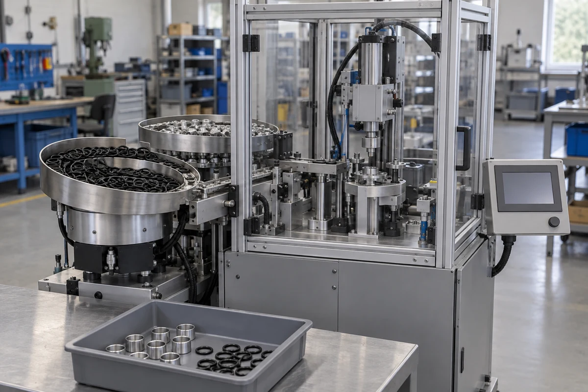
A seal-fitting cell feeds loose rings, positions the mating part and places the ring. This guide examines ZONESUN’s ZS-J0A02: what its listing establishes, how the ring reaches its groove, and what an acceptance run must demonstrate.
Automated assembly is a broader category. The model data here concerns a dedicated O-ring fitting machine; the manufacturer records also include robotic lines, machining services and motion components.
CNFX editorial research · Sources checked October 12, 2026 · 4 sources
What the machine publishes, and what it leaves to your part
The ZS-J0A02 listing describes vibratory feeding, positioning, placement and unloading, controlled by a PLC and HMI. It names valves, connectors and pump bodies as applications; suitability for a particular drawing remains a sample-trial question [1].
OD range is not a fit check
OD 4–50 mm is only the published ring envelope [1]. Submit ID, cross-section, compound, hardness and the part drawing before a tooling quotation.
Rate depends on the part
Ask for sustained accepted output on your samples, including refills, rejected parts and inspection time. The published rate does not establish your production result [1].
Published line (ZS-J0A02)
Value
Production capacity
1,500–3,600 pcs/h; published range, without a reference part or test duration [1]
Yield
>98%; defect definition, sample size and rework treatment not supplied [1]
Ring range
Outside diameter 4–50 mm; not an ID or cross-section range [1]
Supply
AC 220 V ±15%, 50/60 Hz; phase and connection details not stated [1]
0.4–0.8 MPa (4–8 bar); airflow and air-quality requirement not stated [1]
Controls
PLC + HMI touchscreen; controller and sensor models not identified [1]
Listed price on 9 October 2026
US$28,000, 220 V selection, US-dollar storefront; shipping calculated at checkout. A listing price is not a delivered project quotation [1]
02
Follow the ring through the assembly cell
The manufacturer describes these functional blocks [1]. This is a component structure / BOM reference, not an orderable manufacturing BOM. Quantities, part numbers and material grades are not published.
Feed and orient
Bulk rings and lids are arranged and delivered to the assembly station [1].
Position and fit
The placement system brings them to the component; interchangeable tooling accommodates different rings and parts [1].
Monitor and unload
Sensors and PLC control are described alongside automatic unloading. The listing does not identify how rejects are separated [1].
Functional block
Role in this cell
Material / configuration evidence
Vibratory feeding system
Orients and delivers rings and lids to the station [1].
Bowl quantity, contact material and ring anti-tangling method not stated.
Panel material, interlocks and safety-control architecture not stated.
The listing does not establish a robotic manipulator, belt conveyor, vision camera or automatic tool changer as fitted equipment. The described ring-fitting operation does not establish welding, gluing or screwdriving end-effectors.
03
Check the path the ring travels on your part
Use the part drawing to examine the temporary assembly path separately from the finished seal geometry. Parker’s handbook section 2.5 supplies the following assembly guidance [2].
Find the largest diameter the ring must pass
For example a thread, shoulder or groove land between the ring's start position and its groove.
Calculate the temporary stretch
For a circular passage, stretch = (largest diameter passed / free ring ID − 1) × 100%. Editorial examples: 10 mm ID over 14 mm gives 40%; 4 mm ID over 7 mm gives 75%. The latter exceeds Parker’s guideline. An expanding tool does not waive the material limit; revise the path or ring design and validate the chosen compound. Being below 50% alone does not prove a suitable fit.
Check every edge on the path
Mark chamfers, threads and ports on the drawing and send it with samples, so the maker designs the fitting sleeve or mandrel.
Specify the trial condition
Tell the supplier whether your delivered rings are dry or lubricated, and provide the approved lubricant. Treat feeder performance and finished seating as separate observations during the trial.
Temporary stretch
Parker limits assembly stretch to 50% of ID and below the compound’s ultimate elongation [2].
Lead-in geometry
Its piston/rod examples show burr-free 15°–20° chamfers, with lead-in height exceeding ring protrusion [2].
Edges and rolling
Cover sharp threads and edges; large-ID, thin-section rings may roll and develop leakage or spiral failure [2].
Cross-drilled ports
The handbook’s shearing example concerns a spool or rod moving across ports inside a bore. It discusses relocating ports, internal chamfers or a balancing groove [2].
Cleaning and lubricant
Keep sealing glands clean; choose cleaning agents and assembly grease compatible with the elastomer [2].
04
Decide what the inspection must prove
The listing makes a missing/misaligned-ring prevention claim, without a sensor method, false-accept study or leak-test specification [1]. The comparison below is an editorial acceptance framework; it is not the supplied ZS-J0A02 inspection configuration.
Prove detection with known bad parts
Proposed acceptance exercise: prepare a correct reference plus no-ring, off-seat and rolled-ring examples. Agree which defects the supplied system must detect, then record missed defects, false rejects and the route of rejected parts. Do not assume a sensor detects all four cases.
Leak-tightness needs its own station
A sealing decision needs a separately specified leak test, integrated or downstream. The listing’s sensor claim supplies no such test method [1].
Possible check to specify
Acceptance evidence to request
Boundary
Presence detection
Demonstrate detection of missing rings on the actual part.
Signal response alone does not prove seating or sealing.
Position / height measurement
Agree the measurement location and limits against the part drawing.
Hidden cuts or wrong compound need separate evidence.
Vision inspection
Validate the lighting, views and specified visible defects.
A camera does not establish complete hidden-surface or compound inspection.
Leak test
Agree medium, pressure, stabilisation, duration and reject limit.
Passing applies to those test conditions, not every operating condition.
05
Keep first-pass yield separate from reworked output
The listing states yield above 98% without sample size, defect definition or treatment of rework [1].
Count distinct assemblies
Editorial arithmetic example, not a factory case: 1,000 distinct assemblies enter first inspection; 980 pass and 20 fail. First-pass yield = 980 / 1,000 = 98%. Exactly 98% does not demonstrate the listing’s >98% claim.
Track rework separately
If 15 rejected assemblies are refitted and accepted, final accepted output is 995, or 99.5% of the original batch. First-pass yield remains 98%. Re-inspections must not be counted as new assemblies.
Include stops
Feeder jams, tooling changes and recovery after a stop reduce hourly output below the cycle rate.
Write it into acceptance
Agree the run length, defect definitions and the yield formula before the factory acceptance test.
06
Write the missing limits into the machine specification
Use these fields to define the delivered cell. Published ratings are separated from information still needed for a part-specific quotation and acceptance test.
Field
What to specify or obtain
Current model evidence
Cycle time / s
Define one completed assembly, cavities per cycle and included inspection time.
Not stated; hourly output alone does not prove a fitting-cycle duration.
Positioning accuracy / mm
Name datum, measuring method and maximum error; distinguish accuracy from repeatability.
Neither value published.
Payload / kg
Specify part mass and allowable fixture load.
No robot/gripper payload published.
Station count
Obtain a layout naming feeding, fitting, checking and unloading positions.
Count not stated.
Power / kW
Separate rated input from measured operating demand and energy per accepted part.
Agree run length, refill stops and planned service windows.
No 24/7 duty rating established.
Service life / maintenance
Obtain warranty, wear-part replacement criteria and support scope.
No service-life guarantee published.
Noise / dB(A)
Request measurement location, operating condition and noise declaration.
No numerical level published.
Safety documentation
Identify destination rules and machine-specific assessment/validation records.
Listing protective features do not establish certified conformity [1].
Humidity / % RH
Agree environmental and condensation limits in the delivered manual.
No humidity range published.
Cleanliness / enclosure protection
Specify contamination control and any required enclosure rating.
Neither IP54 nor IP65 established by the listing.
A general automation range cannot substitute for a matched machine sheet. Ask the supplier to return this specification against the selected ring, part, tooling and delivered equipment revision.
07
Plan guarding and the risk assessment
ZONESUN describes transparent protective enclosures and emergency stop buttons on the ZS-J0A02 [1].
Risk assessment is the starting point
ISO 12100:2010’s public abstract covers machinery risk assessment and risk reduction. It remains published; its replacement is still a draft [3]. Request the assessment for this cell, including replenishment, clearing jams and maintenance, plus documents appropriate to the destination market.
Safety-related controls are designed to a level
ISO 13849-1:2023 concerns safety-related control design, but does not prescribe a required performance level for this machine [4]. Ask the designer to identify each required safety function and its supporting design/validation evidence. A transparent panel and emergency-stop button do not demonstrate compliance.
08
Make tooling condition and restart checks part of handover
No model operating/service manual was established in the reviewed listing. The following is a proposed handover scope, not a manufacturer maintenance procedure or service interval.
Feeder and fitting surfaces
Ask for the approved cleaning method and wear/replacement criteria for the selected ring compound and tooling.
After changing ring or part
Retain the approved tooling/recipe identity and an agreed reference assembly; demonstrate seating and required inspection again.
After a jam or rejected run
Obtain the isolation, clearing and restart instructions from the supplier. Define what happens to parts left inside the cell and how suspect output is segregated.
Controls and spare parts
Request the electrical/pneumatic drawings, settings backup, alarm meanings and critical-spares list for the delivered revision.
Maintenance and jam-clearing hazards belong in the machine’s lifecycle risk assessment [3]. Do not improvise work inside a running enclosure or invent daily/annual service intervals from a product listing.
09
Copy this RFQ and fill in the brackets
Paste it into your enquiry below or into an email to a maker, then replace every bracket.
Product: automatic O-ring assembly machine, quantity [ ]
Part: drawing [rev], material [ ], parts per hour required [ ]
O-ring: ID × CS [mm], compound and hardness [ ], dry / pre-lubricated [ ]
Path: largest diameter passed [mm] → stretch [%]; threads, ports or sharp edges on path [yes/no]
Inspection: presence / seating / vision / leak test [ ]; reject handling [separate bin, lockout]
Acceptance test: run length [pcs], defect definitions, first-pass yield ≥ [ %] on our parts and rings
Changeover: number of part/ring variants [ ], changeover time target [min]
Utilities: voltage/phase/frequency [ ]; air pressure/flow/quality [ ]
Safety: destination [ ]; risk assessment, safety functions and destination-specific conformity documents
Handover: delivered manual, tooling drawings, cleaning/wear criteria, settings backup, critical spares
Samples: we will send [n] parts and [n] rings for trial
Delivery to [country], target date [date]
9 companies list this product among what they make. Company figures are quoted from each
company's own website; every card states where the relationship came from.
ZONESUN
Foshan, Guangdong (manufacturing entity), CN
The ZS-J0A02 listing describes a dedicated O-ring feeding and fitting cell, PLC/HMI, sensors and interchangeable tooling. Obtain the ring/part trial and delivered documentation; the yield and protective-feature claims are not leak-test or safety-validation evidence.
The reviewed page offers machining, molding, cable manufacture and assembly of mechanical/electronic products with functional testing. This is a product-manufacturing service; it does not establish sale of an automatic O-ring fitting machine.
The current metal-forming catalogue lists coil-to-weld, laser blanking, robotic bending/welding and vehicle-wheel welding lines. These are metal-fabrication processes; no matched O-ring insertion cell was established. The general homepage certification claims were not checked for a particular machine.
Nantong Guosheng Intelligence Technology Group Co., Ltd.
Nantong, Jiangsu, CN
Its intelligent-production catalogue lists engine-block machining, automatic tool processing, horizontal machining-center FMS and new-energy auto-parts processing lines. These are machining/production systems; the reviewed category does not establish a seal-fitting model.
The current catalogue includes gantry robots, robot tracks, automated packaging/palletizing systems, and automation frames and supports. Specify the relevant handling or structural task; a production-line column alone is not a complete assembly cell. No O-ring fitting model was established here.
HGLaser’s current catalogue presents a prismatic-cell module/pack assembly line, laser processing/welding equipment and energy-sector production solutions. Those processes differ from seal fitting. Identify the supplying entity and a task-specific line rather than applying the ZONESUN sheet.
The robotic-assembly page describes integrated conveying, handling, testing, gluing, screw locking and packaging, with configurable line layouts and MES management. It concerns customized robotic lines; no ZS-J0A02-style O-ring model or ring-size range is stated.
The reviewed catalogue supplies ball screws, guide rails, lock nuts, supports, couplings and related motion modules. Automated production lines appear as an application area; that does not establish a complete assembly-machine offering.
The current range includes linear guides/modules, bearing screws and pneumatic grippers. These are motion/handling components for automation; no complete O-ring feeding and fitting cell was established in this review.
Explore company information and manufacturing capabilities, then discuss the scope of your project with a relevant supplier.
Share this page
Compiled and source-reviewed by the CNFX editorial team.
Each manufacturer above links to the page on that company's own website where the product is listed, with the date we checked it. How we source and review
· Page last updated 13 October 2026
Buyer questions
How far can an O-ring be stretched during automatic assembly?
Parker gives a 50% assembly-stretch ceiling and requires remaining below the compound’s ultimate elongation. It is not a universal safe operating stretch or approval of a particular tool. [2]
What chamfer helps automatic O-ring fitting?
The handbook’s piston and rod assembly examples use burr-free 15°–20° lead-ins. Confirm the actual part geometry; this is guidance, not a machine capability rating. [2]
Does a presence sensor prove the O-ring seals?
Only a validated detection method establishes presence for the agreed defects. The ZS-J0A02 listing identifies no leak-test method; a sealing decision needs specified test conditions. [1]
What does a 98% yield claim mean?
The listing says >98% but does not define its calculation. In the editorial example, 980 first-pass successes from 1,000 parts is exactly 98%; reworking 15 rejects changes final acceptance to 99.5%, not first-pass yield. [1]
Sources and what still needs a direct check
Sources checked 2026-10-12. Standards bodies and regulations define the requirements; manufacturer pages show published ranges for those models only. CNFX does not certify products or suppliers.