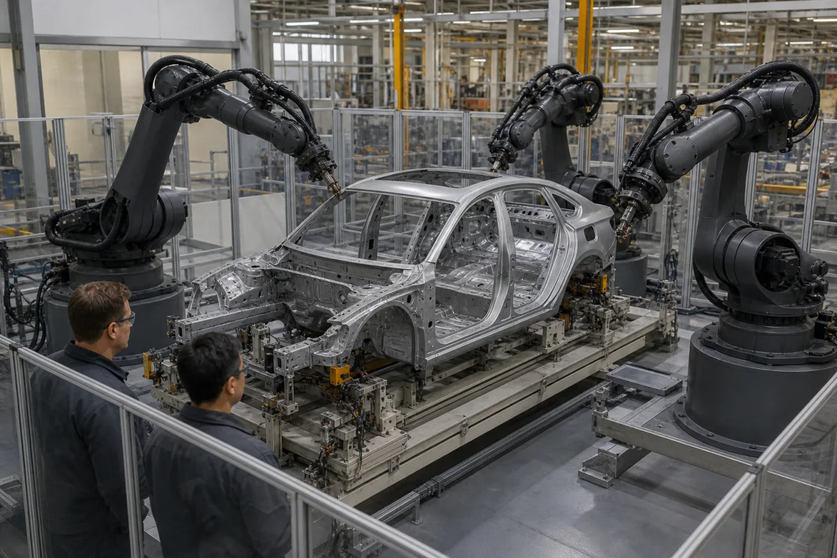
Articulated spot-welding robots for car body-in-white framing stations: 150–235 kg arms, gun dress packs and station cycle time
The large six-axis robots that stand round a car body in the framing and respot stations of a body shop and carry electric spot-welding guns — the 150–235 kg class, the dress pack that feeds the gun, and how many robots a station needs for its cycle
In the body shop the floor, sides and roof of a car are clamped together in a framing station and fixed with spot welds, then the body moves on to respot stations that add the remaining welds. The robots in those stations are large articulated arms, each carrying a spot-welding gun with its cables, cooling water and servo lines. What decides the choice is whether the arm carries the gun with its dress pack, whether the dress pack lets the wrist reach every weld, and whether enough robots fit round the body to finish within the line cycle.
Floor-mounted six-axis articulated robots used to carry spot-welding guns in car body-in-white framing and respot stations: payload with the gun and adapter, reach, wrist torque, axis ranges with integrated dress packs, and the number of robots per station against cycle time. Robots for assembly tasks such as screwdriving, insertion and dispensing are covered on the Assembly robot page; general six-axis arms sized by wrist load on the Robotic manipulator page; self-pierce riveting, flow-drill screwing and bonding of mixed-material bodies on the Mixed-material body-in-white joining line page. Torch cable routing on arc-welding arms is covered on the Robotic arm for welding page. Painting and sealing robots and the welding guns and weld controllers themselves are outside this page.
CNFX editorial research · Sources checked October 13, 2026 · 3 sources
Payload with the gun on: 150–235 kg arms, wrist torque and the dress pack's cost in wrist range
Two published spot-welding arms show the numbers that matter when a gun hangs on the wrist: the payload has to include the gun and its adapter, the wrist torque has to cover the gun's offset centre of gravity, and the dress pack carrying power, water and servo cables has to leave the wrist enough rotation.
Yaskawa states that the SP210 suits a wide range of spot-welding guns, servo-controlled guns with robot-assisted gun alignment among them, and that its slim arm needs no mechanical counterbalance, which keeps moving masses low for higher accelerations; the arm weighs 1,080 kg, runs on a 3 kVA supply and is floor mounted. [1]
ABB builds every IRB 6700 to take Lean ID, an integrated dress pack that routes part of the dress pack inside the robot, and says this makes cable movements predictable for programming and simulation and lengthens service intervals. The price is wrist range: axis 5 goes from ±130° to ±120° and axis 6 from ±360° to ±220° with the Lean ID option. The arm also takes extra loads of 50 kg on the upper arm and 250 kg on the frame of axis 1. [2]
Editorial calculation: with Lean ID the total rotation of axis 6 falls from 720° to 440°, about 39 % less, so gun orientations that need the wrist to wind round more than ±220° have to be planned in simulation before the dress pack is chosen.
Ask for the payload including gun, adapter and dress pack, the wrist torque at the gun's centre of gravity, and the axis 5 and 6 limits with the dress pack fitted.
02
Framing station: four welding robots, about 1 minute per body, and tool changes for handling
Comau and BMW's European patent application EP 0 933 161 A1 describes a framing station of the kind in the photograph: locating gates hold the body sides against the floor panel while programmable robots with electric spot-welding heads, four in the illustrated example, put in a first series of welds that make the body self-supporting, then a second series to complete it. [3]
The patent ties robot count to cycle time. It says the number of welding spots for framing a sedan or coupé body is substantially similar, so once the number of robots at the station is fixed the line cycle time, the duration of each stop, is about the same, e.g. in the order of 1 minute; running a station-wagon body on the same line without adding robots would need about a doubling of the cycle time. [3]
Robots in that station also change roles. At least some of them have automatic tool changers that park the welding head in a magazine beside the robot and pick up a gripping tool, which then places cross members for the other robots to weld. While the robots finish the second series of welds, the locating gates are already receiving the sides of the next body behind moving protective screens. [3]
Editorial note: a robot that doubles as a handler must be sized for the heavier of its welding gun and its gripper, which is why the payload figures in the arm table above are read with the tool, not without it. [3][1]
Ask how many robots the station layout fits round the body, the welds each robot is assigned within the cycle, and whether any robot changes between gun and gripper.
03
Information for body-shop spot-welding robots
Paste it into your enquiry below or into an email to a maker, then replace every bracket.
Station: [framing or respot; body types run; target cycle time]
Gun: [servo or pneumatic; mass and centre of gravity with adapter]
Dress pack: [integrated or external; axis 5 and 6 range needed]
Arm: [payload; reach; mounting; extra loads on upper arm or base]
Tool change: [welding head only, or gun and gripper]
Explore company information and manufacturing capabilities, then discuss the scope of your project with a relevant supplier.
Share this page
Compiled and source-reviewed by the CNFX editorial team.
Each manufacturer above links to the page on that company's own website where the product is listed, with the date we checked it. How we source and review
· Page last updated 13 October 2026
Buyer questions
What payload does a spot-welding robot need?
It must carry the gun with its adapter and dress pack; Yaskawa rates the SP210 at 210 kg including C-adapter, and ABB's IRB 6700 spans 150 to 235 kg. [1][2]
Does an integrated dress pack limit the robot?
On ABB's IRB 6700, Lean ID reduces axis 5 from ±130° to ±120° and axis 6 from ±360° to ±220°. [2]
How long does a framing station take per body?
Comau and BMW's EP 0 933 161 A1 gives a line cycle in the order of 1 minute for sedan or coupé bodies, about doubling if station-wagon bodies ran without more robots. [3]
Can a welding robot also handle parts?
In EP 0 933 161 A1 some robots park their welding head in a magazine and pick up a gripping tool to place cross members. [3]
Sources and what still needs a direct check
Sources checked 2026-10-13. Arm data come from Yaskawa Europe's SP210 page and ABB's IRB 6700 data sheet; the framing station layout and cycle time from a Comau and BMW European patent application.