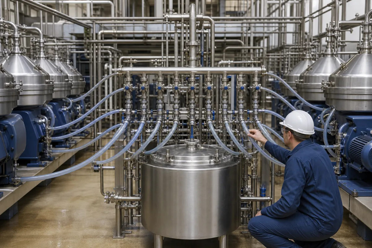
Feed distribution header for a bank of parallel disc separators: equal split, branch balancing and light-phase routing between machines
The header and branch piping that shares one feed tank between two or more disc stack separators · branch-to-header area ratio below 1, balancing restrictions that took a manifold's flow imbalance from over 100 % to under 10 %, and a whey layout that pipes one separator's light phase into the next separator's inlet
When a dairy, whey or oil plant runs two, four or more separators from one balance tank, the piping between tank and machines decides how much each machine receives. If one branch draws more than its share, that separator runs above the flow it was sized for while its neighbour runs below. The header also decides what each separator receives: raw feed only, or raw feed mixed with a phase returned from another machine.
Feed headers, branch lines, balancing valves and transfer lines that divide one product stream between disc stack separators installed in parallel, including lines that route a separated phase from one machine into the inlet of another. The separator itself, its disc stack and equivalent settling area (sigma) sizing are covered on the Disc stacks and disc stack separators page; gum removal from crude vegetable oil is covered on the Oil degumming separator page. The distributor inside the separator bowl is described here only as the point where the header's flow ends.
CNFX editorial research · Sources checked October 13, 2026 · 4 sources
Area ratio below 1 and balancing restrictions in each branch
Zhou et al. (Harbin Engineering University, 2018) studied how one stream divides between the parallel tubes of a heat exchanger header, and their review lists the parameters Wang et al. found to govern the split: inlet flow condition, tube diameter, header diameter, area ratio and flow direction, with gravity insignificant. The flow imbalance arises because pressure is not uniform along the header. [1]
The same review records Bajura and Jones's recommendation that the area ratio, the summed branch area divided by the header area, be kept below 1, and Tong et al.'s finding that enlarging the header diameter improves the distribution. Tong et al. also placed gate-valve-like obstructions in individual branches; in one case the flow imbalance of the untailored manifold exceeded 100 % and fell to less than 10 % after one cycle of the method. In Zhou et al.'s own simulations, changing how far each branch tube projected into the header cut maldistribution by 82 %, 72 % and 68 % in three header diameters according to the abstract (81 %, 69 % and 69 % in the results section, which also gives 81 % at most and 69 % at least), at a pressure drop increase of 2.83 %, 4.83 % and 6.46 %. [1]
Editorial calculation: keeping N equal branches of diameter d below an area ratio of 1 needs a header diameter above d × √N. Taking the 63.5 mm of a DN63.5 separator feed connection as the branch diameter and ignoring wall thickness, four separators need a header above 127 mm and six above about 156 mm. [3]
Editorial note: these figures come from heat exchanger headers feeding rows of tubes; a bank of separators has fewer, longer branches, each ending in a machine with its own inlet resistance. They show which way the geometry pushes the split, not the split a given separator bank will reach.
Ask for a flow meter or a balancing valve on each branch, and for the measured flow to each separator at full header flow.
02
Piping one whey separator's light phase into the inlet of the next
A Tetra Laval patent (US 8,313,786 B2) uses the branch layout itself to raise fat recovery from whey with only two separators connected in parallel, each with its own inlet conduit. [2]
The first separator is run with more flow in its light phase so that more of the smaller fat globules leave with it; that stream is piped into the inlet conduit of the second separator, and the heavy phases of both machines are joined into one conduit. With three separators, the light phases of two are joined and led to the inlet of the third; with four, two pairs can run this way. The patent reports a 5–10 % increase in fat separation for a plant using the method. [2]
Alfa Laval's BM840 bacteria-removing separator describes a related arrangement: depending on the setup, with one or multiple units in series, the bactofugate can be recirculated to the first separator to recover more milk. [3]
If a return line from one separator joins another separator's inlet, the second branch carries more flow than the first; size it and its meter for the combined flow.
03
Where the branch ends: hermetic bottom feed on DN63.5 connections
Alfa Laval's leaflets for two dairy separators give the inlet the header has to connect to. [3][4]
In the BM840, milk is fed from the bottom through the hollow drive spindle into the rotating bowl, where separation takes place between the bowl discs; the leaflet's bowl drawing, which Alfa Laval notes does not necessarily correspond to this model, labels the inlet, distributor and disc stack in that order. The leaflet says the hermetically sealed inlet and outlet prevent oxygen pick-up and that smooth acceleration of the feed in the spindle helps keep fat globule sizes. Product contact parts comply with Regulation (EC) No 1935/2004, product-wetted gaskets are NBR, and the model is available with 3-A certification for centrifugal separators and clarifiers. [3]
Editorial calculation: the D870's 70,000 l/h maximum through the same DN63.5 connection as the BM840's 35,000 l/h nominal means that, for equal pipe size, a branch to a D870 at full rating carries twice the flow and so twice the mean velocity of a branch to a BM840. [3][4]
Separator
Duty
Capacity
Feed inlet
BM840
Removing spores and bacteria from milk
35,000 l/h nominal, 40,000 l/h maximum; 37 kW motor [3]
Explore company information and manufacturing capabilities, then discuss the scope of your project with a relevant supplier.
Share this page
Compiled and source-reviewed by the CNFX editorial team.
Each manufacturer above links to the page on that company's own website where the product is listed, with the date we checked it. How we source and review
· Page last updated 13 October 2026
Buyer questions
How large should the header be compared with the branches?
Manifold studies reviewed by Zhou et al. cite Bajura and Jones's recommendation that the summed branch area divided by the header area stay below 1. [1]
Can valves in the branches even out the flow?
In work by Tong et al. reviewed by Zhou et al., gate-valve-like obstructions in individual branches reduced an untailored manifold's flow imbalance from over 100 % to under 10 %. [1]
Why would one separator's output go into another separator's inlet?
A Tetra Laval patent sends the light phase of one whey separator to the inlet of a second, raising that machine's feed to 0.4–0.8 % fat and reporting 5–10 % more fat separated. [2]
What size is the feed connection on a large dairy separator?
Alfa Laval lists ISO 2852 Tri-Clamp DN63.5 feed inlets on both the BM840 (35,000 l/h nominal) and the D870 (70,000 l/h maximum). [3][4]
Sources and what still needs a direct check
Sources checked 2026-10-13. Manifold flow distribution comes from a peer-reviewed study and review in Frontiers in Energy Research; the phase-routing layout from a Tetra Laval patent; separator inlet and capacity data from Alfa Laval product leaflets.