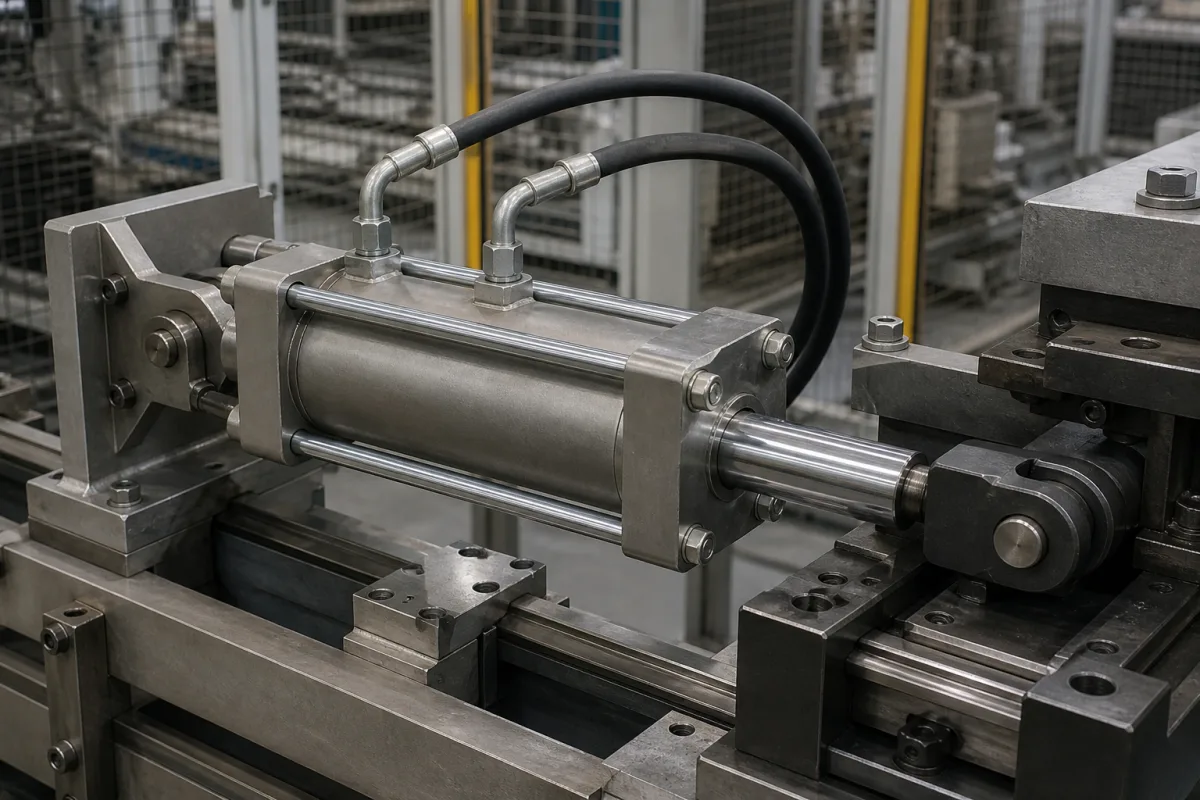
Low-pressure hydraulic tie-rod cylinder (NFPA cylinder for 750–1,500 psi oil and air-over-oil circuits)
Low-pressure hydraulic tie-rod cylinders · run from a 750–1,500 psi pump circuit or from shop air through an air-oil tank or air-hydro converter for smooth, stiff motion
A low-pressure hydraulic cylinder is a tie-rod cylinder with steel end caps, a honed and chrome-plated barrel, a hardened rod and oil-compatible seals, rated for hydraulic oil at moderate pressure. It sits between an air cylinder and a heavy-duty hydraulic cylinder: it is driven by a small hydraulic unit, or by shop air pushing on oil in an air-oil tank or air-hydro converter, where oil's incompressibility gives steadier speed and mid-stroke stops that air alone cannot hold. The buying questions are the pressure rating at your bore, how the oil will be supplied, the tank or converter volume against the cylinder's displacement, and rod guidance on long strokes.
Square-head tie-rod hydraulic cylinders rated for low hydraulic pressure (about 750 to 1,500 psi) and their use with air-oil tanks and air-hydro converters, where oil pressure equals the supply air pressure. Air-only cylinders are covered on the Pneumatic cylinder page; air-over-oil intensifiers that multiply air pressure on the Hydraulic/pneumatic actuator page (hydro-pneumatic intensifier cylinder); heavy-duty single-rod cylinders and their mountings on the Hydraulic cylinder page; excavator boom cylinder assemblies on their own page. Piston rods and honed barrels sold as parts are separate products.
CNFX editorial research · Sources checked October 12, 2026 · 4 sources
Pressure rating falls with bore: 1,500 psi up to 3¼ in, 750 psi at 6 in
Milwaukee Cylinder's Series LH is a catalogued example of the type. Its nominal pressure runs from 750 to 1,500 psi depending on bore, against 3,000 psi hydraulic service for the same maker's heavy-duty Series H and 250 psi air service for its Series A pneumatic cylinders. [1][3]
The catalogue's standard specification is square-head tie-rod construction, hydraulic oil as the standard fluid, −20 to +200 °F with nitrile (Buna-N) seals, bores of 1½ to 6 in, rods of ⅝ to 4 in, 17 standard mounting styles, cushions at either or both ends and seven standard rod-end styles. The barrel is chrome-plated, honed steel tubing; the piston is fine-grained iron alloy with two U-cup seals; the rod is hardened, plated high-strength steel. [1]
Editorial calculation: a 2 in bore has 3.14 in² of piston area, so at its 1,500 psi rating it pushes about 4,700 lbf (about 21 kN). The catalogue's pull-stroke deduction for a ⅝ in rod is 461 lb at 1,500 psi [1], leaving about 4,250 lbf on the pull stroke. Above the rating, Milwaukee asks that the application be described in the order. [1]
Give the bore, rod diameter, stroke, mounting style, rod-end style, cushions, the highest system pressure including relief-valve setting, the fluid and its temperature.
02
Air over oil without intensification: air-oil tanks and air-hydro converters
When a low-pressure hydraulic cylinder is driven from shop air, the oil pressure equals the air pressure; the gain is in motion quality, not force. SMC describes its CCT air-hydro unit as a converter and valve unit that converts air pressure to an equivalent hydraulic pressure for operating an actuator, so that despite using pneumatic equipment the drive performs similarly to a hydraulic unit, avoiding the compression characteristics of air. [4]
Milwaukee lists three jobs for an air-oil tank: making up oil lost from the hydraulic side, providing hydraulic pressure to return the cylinder, and giving entrapped air a way out. The tank holds air on top of oil, with the air at line pressure from the same supply. [2]
Sizing follows the cylinder: if the tank is the pressure source for returning the cylinder, its volume must exceed the cylinder's total displacement, otherwise oil is pushed into the air line; Milwaukee advises choosing a tank volume equal to or slightly greater than the cylinder volume. [2] Editorial calculation: a 2 in bore with a 10 in stroke displaces 3.14 × 10 ≈ 31 in³ on the cap side, so the tank needs a usable volume of at least that; at 100 psi air the same cylinder pushes only about 314 lbf, which is why air-over-oil suits light, controlled feeds, while higher force calls for a pump or an intensifier.
Sight gauge in an aluminium shield; baffles in both end caps to limit churning, foaming and aeration; must be used vertically [2]
State the air pressure available, the cylinder bore and stroke on both sides, whether the tank also returns the cylinder, mounting orientation, and the speed control and mid-stroke stop you need.
03
Long strokes: when a stop tube is needed and how much
A rod that extends far from its bearing loads the bushing and piston as a lever. Milwaukee's Series LH catalogue uses a stop tube, a spacer between the rod end cap and the piston, to keep the bearing load acceptable on long-stroke or poorly guided cylinders. [1]
The rule in the catalogue: compute a length K from the mounting case (for mounting cases 1, 4 and 8 in its figure, K = 4 × (stroke + rod stick-out)). If K exceeds 40 in, a stop tube is required, with 1 in of stop tube for each 10 in, or fraction, above 40 in; the cylinder's overall length grows by the stop tube length, and the stop tube is added to K before the final rod size is chosen. [1]
Editorial calculation: a 12 in stroke with 3 in of rod stick-out in one of those mounting cases gives K = 4 × 15 = 60 in, 20 in over the limit, so 2 in of stop tube and a cylinder body 2 in longer than the stroke alone would suggest.
For service, the Series LH retainer plate and rod bushing can be removed externally without disturbing the tie-rod torque, though Milwaukee's wording shows this does not cover every standard model, so confirm it for yours. The rod seal combines spring-loaded vee rings, a bronze bushing and a double-lip wiper. [1]
Ask the supplier to check K for your mounting and rod end and to state the stop tube length and the resulting overall length.
04
Data for a low-pressure hydraulic cylinder quotation
Paste it into your enquiry below or into an email to a maker, then replace every bracket.
Cylinder: [bore; rod diameter; stroke; mounting style; rod-end style; cushions]
Pressure: [maximum system pressure; relief setting]
Drive: [hydraulic unit, air-oil tank or air-hydro converter; air pressure]
Oil: [type; viscosity; temperature range]
Guidance: [rod stick-out; side load; stop tube]
Documents: [pressure rating confirmation; seal material; test record]
Explore company information and manufacturing capabilities, then discuss the scope of your project with a relevant supplier.
Share this page
Compiled and source-reviewed by the CNFX editorial team.
Each manufacturer above links to the page on that company's own website where the product is listed, with the date we checked it. How we source and review
· Page last updated 13 October 2026
Buyer questions
What pressure is a low-pressure hydraulic cylinder rated for?
Milwaukee Cylinder's Series LH is rated 750 to 1,500 psi depending on bore: 1,500 psi for 1½ to 3¼ in bores, 1,000 psi at 4 in and 750 psi at 6 in. [1]
Can a hydraulic cylinder run from compressed air?
Yes, through an air-oil tank or air-hydro converter; SMC's CCT converts air pressure into an equivalent hydraulic pressure of 0 to 0.7 MPa, so force equals that of an air cylinder of the same bore. [4]
How big must the air-oil tank be?
Milwaukee says that if the tank returns the cylinder its volume must exceed the cylinder's total displacement, and advises a tank volume equal to or slightly greater than the cylinder volume. [2]
When does a long-stroke cylinder need a stop tube?
In Milwaukee's method, when the calculated K length exceeds 40 in; add 1 in of stop tube for each 10 in or fraction above 40 in. [1]
Sources and what still needs a direct check
Sources checked 2026-10-12. Milwaukee Cylinder and SMC are makers describing their own cylinders, tanks and converters; ratings are catalogue statements.