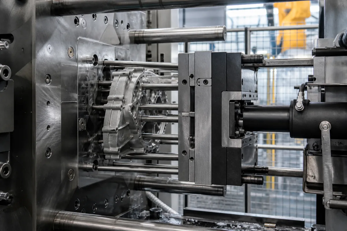
Ejection mechanism for high-pressure die casting: ejector pins that push the casting off the die without marking, bending or sticking
Ejection in high-pressure die casting · Ejector plate and pins that push the casting off the moving die and keep it from bending, pin marks within ±0.381 mm, pin flash and bumping, 1–2° draft for aluminium, and soldering that makes castings stick
This page covers the ejection mechanism of high-pressure die casting dies: the ejector plate in the moving half, its ejector pins and return pins, and the cylinder that drives them after the die opens. Ask three things first: where the pins go and what marks and flash they may leave, how draft, ribs and bosses keep ejection force from bending or bumping the casting, and what keeps aluminium from soldering to the pins and cavity.
Ejection systems of die casting dies: ejector plates, ejector pins and return pins, and their effect on the casting. Cavity inserts are covered on the Die-casting mould cavity insert page, the moving half's die steel and heat treatment on the Moving die half page, ejector pins as bought parts on the Mould ejector pin page, and complete die casting machines on the High-pressure die casting machine page. Ejection in plastic injection moulds and injection drives are outside this page.
CNFX editorial research · Sources checked October 12, 2026 · 4 sources
Ejector pins push the casting off and keep it straight; their marks and flash are part of the spec
NADCA's 2021 Product Specification Standards state that movable ejector pins must be used to eject a die casting and leave a residual pin mark: with each cycle the die opens and the ejector plate in the ejector half moves all pins forward to release the casting, which is then removed manually or mechanically, and the pins also keep the casting from bending. Pin locations are at the die caster's option subject to the customer's agreement and should be discussed before die design where cosmetics matter; number, size and location vary with casting size and complexity; pin diameters should be as large as possible to reduce bending or breaking. Pin marks may be raised or depressed 0.015 in (0.381 mm), raised marks are preferred for production, and larger castings may need more. [1]
Pin marks are surrounded by flash; NADCA's default is to leave it on unless it is objectionable to the end use; it may be specified as crushed or flattened (and may then flake off in use), and should be fully removed by machining or scraping only when requirements justify the cost. [1] A study of a die-cast aluminium gearbox shell set the parting surface so the casting stays on the moving die after opening to allow ejection, with the die opening, then core pulling, then ejection. [4]
Give the die maker the casting drawing with cosmetic and sealing surfaces marked, wall thicknesses, ribs and bosses, the alloy, the die casting machine and its ejector stroke and force, cores and slides, and the acceptable pin mark height and flash treatment.
02
Bumping, draft and soldering: why castings resist the pins
NADCA notes that pins on a flat surface can make the opposite side bulge, called bumping, and lists remedies: thicker walls, locally if needed; pins near walls so ribs share the force; pins on top of ribs; more draft; and bosses where the pins sit. [1] Dynacast explains that draft reduces friction between part and tool during ejection, without which parts can be stripped, dented or stuck, and that standard aluminium castings take 1–2° of draft because the metal is abrasive, against 0.5° for zinc. [2]
Kohlhepp and co-authors, in Materials, studied die soldering by dipping H13-type 1.2343 hot-work steel ejector pins, 12 mm in diameter and preheated to 300 °C, in aluminium melts at 710 °C for 360 s; they cite work showing that high melt speed washes the protective coating or lubricant off the die surface so the melt contacts the steel and builds intermetallic layers, and note that adding manganese, the established remedy for low-iron alloys, needs up to 0.8 wt.%, which adds brittle phases and lowers ductility. [3]
Editorial calculation: on a 50 mm deep aluminium wall, 1° of draft tapers each side by about 0.87 mm and 2° by about 1.75 mm, the clearance the casting gains as soon as the pins start to move it.
03
Send the casting, alloy and machine data together
Paste it into your enquiry below or into an email to a maker, then replace every bracket.
1 company lists this product among what they make. Company figures are quoted from each
company's own website; every card states where the relationship came from.
DGMF Mold Clamps Co., Ltd.
Manufacturing site to be confirmed for the order
Lists ejection mechanism components among its mould clamps, hopper dryer parts and other moulding components.
Explore company information and manufacturing capabilities, then discuss the scope of your project with a relevant supplier.
Share this page
Compiled and source-reviewed by the CNFX editorial team.
Each manufacturer above links to the page on that company's own website where the product is listed, with the date we checked it. How we source and review
· Page last updated 13 October 2026
Buyer questions
How much can an ejector pin mark stand proud on a die casting?
NADCA's guideline allows pin marks raised or depressed 0.015 in (0.381 mm), with raised marks preferred and more allowed on larger castings. [1]
How do you stop ejector pins bumping a flat casting?
NADCA lists thicker walls, pins near walls or on ribs, more draft and bosses at the pin locations. [1]
Why do aluminium castings stick to ejector pins and dies?
A Materials study notes that fast melt washes off the protective coating so aluminium reacts with the die steel and builds intermetallic layers (soldering). [3]
Sources and what still needs a direct check
Sources checked 2026-10-12. NADCA's standard (as hosted by a die caster) and Dynacast give design guidance; two peer-reviewed studies cover soldering and die design.