Editorial Technical Reference

Mixing Impeller

This page explains how Mixing Impeller is classified within Machinery and Equipment Manufacturing. Technical values and manufacturer relationships are research references; confirm the current specification and supplier evidence for each order.

Technical Definition & Core Assembly

A rotating component within a mixing tank that agitates and homogenizes coating slurry through fluid movement.
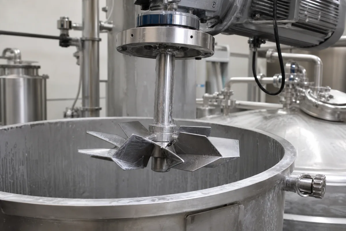
Representative product image. Confirm appearance and specifications with the manufacturer.

Product Specifications

Technical details and manufacturing context for Mixing Impeller

Definition
The mixing impeller is a critical mechanical part of a coating slurry mixing tank, designed to create controlled fluid motion that ensures uniform distribution of solid particles, pigments, and additives within the liquid medium. It directly influences mixing efficiency, prevents sedimentation, and maintains slurry consistency for downstream coating processes. The impeller is typically mounted on a shaft and driven by a motor, converting rotational energy into kinetic energy in the fluid. Its blade geometry—whether axial, radial, or mixed flow—generates specific flow patterns such as pumping, shearing, or turbulence, which promote particle suspension, dispersion, and blending. Available materials include stainless steel (e.g., 304, 316L), carbon steel, and specialty alloys for corrosion resistance. Key parameters include impeller diameter (200–1200 mm), rotational speed (50–500 rpm), power rating (1.5–45 kW), operating temperature (-10 to 120 °C), operating pressure (0.1–1.6 MPa), material grade (304/316L, per ASTM A240), surface roughness (Ra 0.8–3.2 μm), balance quality grade (G2.5–G6.3, per ISO 21940-11), weight (5–150 kg), and maximum slurry viscosity (500–5000 mPa·s). These values are reference ranges and must be confirmed for the specific model and application. The impeller's design and selection depend on tank geometry, slurry properties, and process requirements. Proper installation, alignment, and balancing are essential to minimize vibration and wear. Regular inspection for erosion, corrosion, and fatigue is recommended. Failure to maintain the impeller can lead to reduced mixing efficiency, uneven slurry, and potential damage to downstream equipment. Always verify model-specific values and standards with the legal manufacturer or supplier.
Working Principle
The impeller rotates via a connected shaft and motor, converting rotational energy into kinetic energy in the fluid. Its specific blade geometry (e.g., axial, radial, or mixed flow) generates flow patterns—such as pumping, shearing, or turbulence—that promote particle suspension, dispersion, and blending of the coating slurry components. The rotation creates a pressure difference, drawing fluid into the impeller and discharging it radially or axially, depending on the blade design. This circulation ensures that solids remain suspended and that all components are uniformly mixed. The impeller's speed and diameter determine the flow rate and shear forces, which must be matched to the slurry's viscosity and the tank's size to achieve optimal mixing without excessive splashing or energy consumption.
Common Materials
Stainless Steel (e.g., 304, 316L), Carbon Steel, Specialty Alloys (for corrosion resistance)
Technical Parameters
ParameterTypical rangeNotes & selection driver
Impeller Diameter200–1200 mmDetermines tank coverage and mixing intensity
Rotational Speed50–500 rpmHigher speeds increase shear but may cause splashing
Power Rating1.5–45 kWMatches motor to slurry viscosity and tank size
Operating Temperature-10–120 °CAbove 120°C may degrade elastomer seals
Operating Pressure0.1–1.6 MPaBelow 0.1 MPa insufficient flow; above 1.6 MPa may damage seals
Material Grade304/316L316L for corrosive or food-grade applicationsASTM A240
Surface RoughnessRa 0.8–3.2 μmSmoother finish reduces fouling and eases cleaning
Balance Quality GradeG2.5–G6.3Higher grade reduces vibration and bearing wearISO 21940-11
Weight5–150 kgAffects handling and shaft loading
Max Slurry Viscosity500–5000 mPa·sAbove this range, mixing becomes inefficient

Ranges are indicative industry figures for RFQ preparation, not a supplier commitment. Confirm every value and standard with the legal manufacturer before ordering.

Components / BOM
  • Blade Part
    Primary surface that contacts and imparts energy to the fluid, creating flow and shear.
    Material: Stainless Steel
  • Hub
    Central mounting point that connects the blades to the drive shaft, transmitting torque.
    Material: Steel Alloy
  • Shaft Connection Part
    Interface (e.g., keyway, clamp) that secures the impeller to the mixing tank's drive shaft.
    Material: Steel

Applied To / Applications

This component is essential for the following industrial systems and equipment:

Industrial Ecosystem & Supply Chain Structure

Complementary Systems
Downstream Applications
Specialized Tooling

Application Fit & Sizing Matrix

Operational Limits
pressure: Atmospheric to 10 bar
flow rate: Up to 500 m³/h
temperature: -10°C to +120°C
slurry concentration: Up to 60% solids by weight
Media Compatibility
✓ Water-based coating slurries ✓ Solvent-based coating systems ✓ Ceramic/polymer composite slurries
Unsuitable: Highly abrasive slurries with >60% hard particles (e.g., silica sand)
Sizing Data Required
  • Tank volume (m³)
  • Desired mixing intensity (Reynolds number or power number)
  • Slurry viscosity (cP)

Reliability & Engineering Risk Analysis

Failure Mode & Root Cause
Fatigue cracking
Cause: Cyclic stress from turbulent flow, material defects, or improper welding leading to crack initiation and propagation at stress concentration points like blade roots or welds.
Corrosion-erosion
Cause: Combined chemical attack and mechanical wear from aggressive process fluids, improper material selection for the service environment, or inadequate protective coatings.
Maintenance Indicators
  • Excessive vibration or unusual noise (grinding, knocking) during operation indicating imbalance, wear, or loose components.
  • Visible cracks, pitting, or material loss on impeller blades or hub observed during inspection.
Engineering Tips
  • Implement dynamic balancing after any repair or modification and conduct regular vibration analysis to detect early imbalance or structural issues.
  • Select corrosion-resistant alloys (e.g., duplex stainless steels, nickel alloys) matched to the process chemistry and consider protective coatings or cathodic protection where applicable.

Indicative industry ranges for design and RFQ preparation. Confirm the exact figures and applicable standard with the manufacturer before specifying.

Compliance & Manufacturing Standards

Applicable Standards
ISO 2858:2012 - End-suction centrifugal pumps (Designation, nominal duty point and dimensions) ANSI/ASME B73.1-2012 - Specification for Horizontal End Suction Centrifugal Pumps for Chemical Process DIN 24256:1986 - End-suction centrifugal pumps; nominal duty point, main dimensions

Quoted from the published standard.

Manufacturing Precision
  • Bore diameter: +/-0.025mm
  • Impeller blade thickness uniformity: +/-0.1mm
Quality Inspection
  • Dye Penetrant Test for surface crack detection
  • Dynamic Balancing Test to ISO 1940-1 Grade G6.3

Manufacturers of Mixing Impeller

Manufacturer profiles associated with Mixing Impeller.

Sourcing Mixing Impeller from China?
Tell us your specification and target quantity — we will match it against manufacturer records and come back with the factories that fit.
Request manufacturers We manufacture this

Manufacturer listings support early research and capability understanding. They are not certification, ranking, or transaction guarantees.

Technical documentation
Request current drawings, revision history, and a signed specification sheet.
Manufacturing capability
Verify equipment lists, process limits, capacity, and representative production evidence.
Inspection readiness
Confirm test methods, calibrated equipment, sampling plans, and traceable reports.
Supplier transparency
Check the legal entity, factory address, ownership, certifications, and direct contacts.

CNFX does not score or rank suppliers. Buyers must verify all claims and documents with the legal manufacturer before ordering.

Supply Chain Compatible Machinery & Devices

Automated Powder Coating System

Integrated industrial system for applying dry powder coatings to metal substrates.

Explore Specs →
Centrifugal Pump Impeller

The centrifugal pump impeller is a critical rotating component that converts mechanical energy from the motor into kinetic energy in fluid systems.

Explore Specs →
High-Precision CNC Laser Cutting Machine

Computer-controlled industrial machine using focused laser beams to cut sheet metal with micron-level accuracy.

Explore Specs →
Industrial-Grade Hydraulic Cylinder Piston Rod

This industrial-grade piston rod is a precision-ground cylindrical component designed for use in hydraulic cylinders.

Explore Specs →

Frequently Asked Questions

What are the typical materials used for mixing impellers?

Common materials include stainless steel (e.g., 304, 316L), carbon steel, and specialty alloys for corrosion resistance. The choice depends on the slurry's corrosiveness and application requirements.

How do I select the right impeller diameter and speed?

Impeller diameter (200–1200 mm) and rotational speed (50–500 rpm) are selected based on tank size, slurry viscosity, and desired mixing intensity. Higher speeds increase shear but may cause splashing. Always confirm with the manufacturer for your specific application.

What standards apply to mixing impellers?

Relevant standards include, ASTM A240 for material grade, and ISO 21940-11 for balance quality. These are verification references, not proof of compliance.

What are the signs of impeller wear or failure?

Signs include reduced mixing efficiency, uneven slurry consistency, increased vibration, and unusual noise. Regular inspection for erosion, corrosion, and fatigue is recommended. Replace the impeller if damage is detected.

Data Basis

Editorial classification, named public sources where available, and source-reviewed manufacturer records.

Preliminary Technical Classification
This page supports structured research, RFQ preparation, and supplier evaluation. It does not replace buyer-led supplier qualification, standards review, or technical approval.
Buyer enquiry

Request manufacturing insight for Mixing Impeller

Ask for use case, specification boundaries, supplier type, and RFQ preparation information for this product.

Where it goes
Straight to the CNFX editorial desk, and to the manufacturer if this product is linked to a claimed profile. Nothing is broadcast to a supplier list.
Your details stay here
We do not sell or rent enquiry data, and we do not add you to a mailing list. Used only to answer this request.
No commission, no middleman
CNFX is a directory. We take no cut of any order and never negotiate on a supplier's behalf.
What we don't claim
A listing is not an endorsement. Qualify every supplier and verify every figure yourself before ordering.

Your business information is used only to process this request.

Thank you! Your message has been sent. We'll respond within 1–3 business days.
Sorry, we couldn't send your message. Please try again, or email us at contact@cnfx.com.

Need to Manufacture Mixing Impeller?

Compare manufacturer profiles with relevant product and process capability.

Previous Product
Mining Loader
Next Product
Mixing Rotor
Get QuotesChat