Bowl surface, part finish and noise in a part feeder
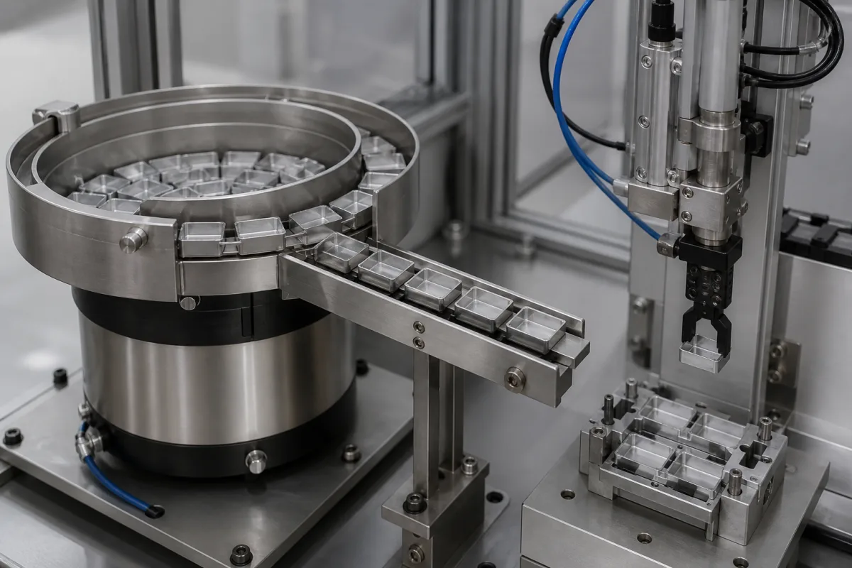
The illustrated feeder carries thin-walled, polished square housings round a stainless bowl and down a linear track to a gripper that sets them in a nest. Parts like these show every scuff, and a steel bowl feeding them is also a noise source. A feeder maker's article on coatings, the UK Health and Safety Executive's noise guidance and case study, and a patent for a feeder enclosure cover the surface and noise side of the job.
Covers the bowl and track surface of vibratory part feeders feeding assembly stations: friction and surface finish, linings for cosmetic and delicate parts, hard coatings for abrasive parts, coating wear and relining, and noise control by lining and enclosure. Bowl feeder rate, tooling and drive selection are on the Vibratory bowl feeder page (4186); dedicated versus flexible feeding on 2805; linear tracks and escapements on 3467; feeder vibration drives on 4601; gripper force and fingers on 4660 and 4125; hopper elevators that refill the bowl on 4934.
CNFX editorial research · Sources checked October 13, 2026 · 4 sources
The surface sets the friction, and friction sets the feeding
RNA Automation's article on feeder coatings starts from the mechanism: a vibratory bowl drives parts forward through friction, so too little and parts vibrate in place or bounce, too much and they stick, jam on tooling and cut throughput.
RNA also notes that an elastomeric lining reduces bounce, so parts settle more consistently on the track, which matters when a robot picks from the end of it as in the illustration.
Coating choice therefore starts from the part, not from a colour swatch: its material, whether it is abrasive, delicate, light or oily, the feed rate, and whether the line is food-grade or heavy industrial.
Surface
What RNA says about it
Polished stainless
Relatively low friction; light plastic parts can 'slip' (bowl moves, part stays) or 'dance' (bounce without progress)
Stainless finishes
Grit-blasted, mirror-polished, electropolished and shot-peened stainless each give a different friction profile
Mixed finishes in one bowl
Polished where parts must slide into a tooling gate, textured where they must hold orientation through it
High-traction polyurethane
More grip lets the bowl run at lower amplitude while keeping a higher feed rate
02
Protect the part or protect the bowl
RNA frames the coating as a balance between two kinds of damage: the bowl marking the part, and the part wearing the bowl.
Coatings wear, and RNA lists what follows: lower feed consistency, more jams or recirculation, higher vibration settings, orientation instability and more part marking. Its practical sign is operators turning the controller up to hold the same output; visually, exposed metal on a lined bowl or a textured track worn mirror-smooth.
RNA's recommendation is to record a baseline surface profile at commissioning and re-measure it at set intervals, so relining is planned rather than forced by a breakdown.
Case
Risk
Surface RNA specifies
Decorative plastic caps, polished medical devices, precision-machined parts
Scuffing, witness marks, edge damage from bare steel
Soft linings such as Habasit or soft-grade polyurethanes to cushion impact
Act like sandpaper and wear grooves ('tracking') into the bowl, ruining orientation precision
High-shore polyurethanes, plasma coatings or hard chrome
For the polished aluminium housings in the illustration, the soft-lining row applies; the RFQ should state the cosmetic standard the part must meet after feeding (editorial reading).
03
Noise: lining, enclosure and the limits
Under the UK Noise Regulations, HSE's guide sets the lower exposure action value at a daily or weekly personal exposure of 80 dB and the upper at 85 dB, with peak sound pressure values of 135 and 137 dB(C).
A 5 dB reduction cuts the sound energy to 32% of what it was, yet 91 dB is still 6 dB above the 85 dB upper action value for a full-shift exposure (Editorial calculation, 10^(−5/10) = 0.32).
The 1976 patent sets out the limit of a lining on its own: it notes that plastic linings used against bowl noise wore out, and that parts still impact one another; its enclosure keeps a parts exit and lets the operator see the bowl, with the Mylar film keeping oil and dust out of the foam.
Measure
Result
Source
Tube-fitting maker's bowl feeders moving metal parts
96 dB before treatment
HSE case study
Bowl inside faced with 3 mm shotblast rubber, contact adhesive
91 dB after, a 5 dB reduction; £70 per feeder including in-house labour
HSE case study
Enclosure: 1–2 in acoustic foam behind 0.001 in aluminised Mylar film
Insertion loss of 20 dB or more, measured on a commercial unit
US 3,960,237 (1976)
Noise sources named
Parts striking each other, not only the bowl; the magnetic drive under the bowl
US 3,960,237
04
What to give a part feeder supplier about surface and noise
Paste it into your enquiry below or into an email to a maker, then replace every bracket.
Give the part material, finish and the cosmetic standard after feeding, whether parts are oily, abrasive or light, required feed rate, line environment (food-grade, cleanroom, heavy industry), and the maximum noise allowed at the operator position. Ask for the bowl and track surface finish by section, lining or coating type and hardness, expected relining interval, measured noise level with your parts, and enclosure options with parts exit and access.
Explore company information and manufacturing capabilities, then discuss the scope of your project with a relevant supplier.
Share this page
Compiled and source-reviewed by the CNFX editorial team.
Each manufacturer above links to the page on that company's own website where the product is listed, with the date we checked it. How we source and review
· Page last updated 13 October 2026
Buyer questions
Why do parts slip or bounce in a vibratory bowl?
RNA explains that polished stainless has relatively low friction, so light plastic parts can slip or dance; textured finishes or polyurethane linings add grip. [1]
How do you stop a feeder marking polished parts?
RNA specifies soft linings such as Habasit or soft-grade polyurethanes for decorative and precision parts that would scuff on bare steel. [1]
How much does lining a bowl feeder cut noise?
In an HSE case study, facing the bowl with 3 mm shotblast rubber took the level from 96 dB to 91 dB at £70 per feeder. [2]
What noise limits apply to a feeder station?
HSE's guide gives lower and upper exposure action values of 80 and 85 dB daily or weekly personal exposure, and 135 and 137 dB(C) peak. [3]
Do enclosures help?
US 3,960,237 describes a foam-lined feeder enclosure with a measured insertion loss of 20 dB or more. [4]
Sources and what still needs a direct check
Sources checked 2026-10-13. A feeder maker's article on bowl coatings (RNA Automation), the UK HSE's noise-at-work guide and a bowl-feeder noise case study, and a 1976 patent for a feeder sound enclosure.