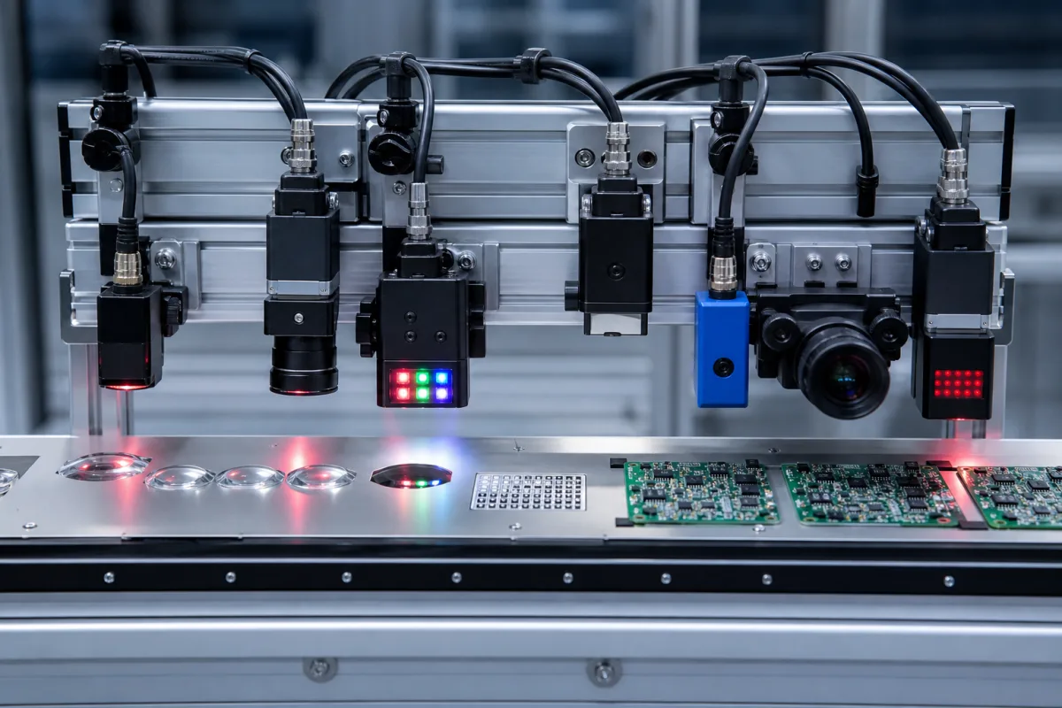
Sensor array of side-by-side photoelectric sensors: how many heads can share one rail without reading each other's light
Optical sensors mounted side by side on one rail or bracket · mutual interference between neighbouring emitters, the response time spent preventing it, and how stacking more amplifier units lowers the allowed ambient temperature and output current
A sensor array here means a group of optical sensors working side by side: a row of heads on one profile above a conveyor, fibre amplifiers clipped together on a DIN rail, or two multi-beam units placed next to each other to cover a wider zone. Each sensor is fine on its own; the problems appear when they are packed together. A neighbour's emitter can trigger a false output, the cure slows every sensor down, and a tall stack of amplifiers runs hotter than one unit. Those three limits decide how many sensors fit in one array and how fast it can be.
Arrays of photoelectric and fibre-optic sensors mounted close together on a common rail, bracket or DIN track, including gang-mounted fibre amplifier stacks and side-by-side multi-beam picking sensors, with their mutual-interference prevention, speed modes, unit-count limits and stacking derating. Single photoelectric sensors chosen by sensing mode, range and housing are covered on the Photoelectric sensor page; cleanroom particle, viable and climate monitoring networks on the Cleanroom environmental monitoring system page; safety light curtains for guarding on the Safety light curtains page; thermocouple arrays in mould cavities on the Temperature sensor array page.
CNFX editorial research · Sources checked October 12, 2026 · 3 sources
Interference prevention switches off in the fastest modes: 0, 4, 8 or 10 neighbours depending on response time
Fibre amplifier data sheets state how many units can sit together without reading each other's light, and the count is tied to the speed mode. Omron's E3NX-FA lists 0 units in super-high-speed mode (30 µs operate or reset on single-output models, 32 µs on two-output models) and 10 units in high-speed (250 µs), standard (1 ms) and giga-power (16 ms) modes; a footnote confirms the function is disabled in super-high-speed mode. [1]
Keyence's FS-N13P gives the same pattern with different steps: 0 units at HIGH SPEED (50 µs), 4 at FINE (250 µs), and 8 at TURBO (500 µs), SUPER (1 ms), ULTRA (4 ms) and MEGA (16 ms), with the number doubled when the double setting is selected. [2]
Panasonic's NA1-5 and NA1-PK5 picking sensors, five-beam units with a 25 mm beam pitch, solve it by emission frequency instead: setting the two units to different frequencies lets two be mounted close together. The response time is listed as 10 ms or less, and with interference prevention in use as 30 ms or less in the light state and 13 ms or less in the dark state. [3]
Editorial calculation: moving from Omron's 30 µs mode, where no neighbour is protected, to its 250 µs mode, where ten are, makes each response about eight times longer (250 / 30 ≈ 8.3). For a target assumed to move at 1 m/s, 250 µs corresponds to 0.25 mm of travel and 16 ms to 16 mm. On the Panasonic unit the light-state response with interference prevention is three times the plain figure (30 / 10). [1][3]
The protection also has stated gaps. Omron notes that it does not work in combination with its E3C, E2C or E3X amplifiers, and that excessive received light can stop it working properly, in which case the threshold should be raised. [1]
List every sensor in the array with its model and speed mode, mark which ones face each other or overlap, and ask the supplier to confirm the interference-prevention count for that exact mix rather than for one model alone.
02
A 30-unit amplifier stack is rated to 40 °C: ambient temperature and output current fall as units are added
Clipping amplifiers together on a DIN rail changes their ratings. Omron's E3NX-FA allows up to 30 connected units; on the version with a −25 °C lower limit, the operating range is −25 to 55 °C for groups of 1 or 2 units, −25 to 50 °C for 3 to 10, −25 to 45 °C for 11 to 16 and −25 to 40 °C for 17 to 30, and the load current per output drops from 100 mA maximum in groups of 1 to 3 units to 20 mA maximum in groups of 4 to 30. [1]
Keyence's FS-N13P allows up to 16 units in total, counting a two-output unit as two. Its ambient rating is −20 to +55 °C with one or two more units connected, −20 to +50 °C with 3 to 10 more and −20 to +45 °C with 11 to 16 more, and Keyence states that all these ratings assume the unit is mounted on a DIN rail on metal sheeting. [2]
Each unit in the stack also draws its own supply current: Omron lists 960 mW maximum (40 mA) at 24 VDC for its standard models in normal mode, and Keyence 1,050 mW or less (42 mA maximum at 24 V) for the FS-N13P in normal mode. [1][2] Editorial calculation: 16 Keyence units at 42 mA each would draw up to about 0.67 A at 24 V before any load current, which belongs in the sizing of the panel's 24 V supply.
Wider arrays of multi-beam sensors need the same check at a larger scale. Panasonic gives the NA1-5 a sensing range of 0.2 to 3 m and the NA1-PK5 0.1 to 1.2 m, each with five beam channels, and lets the output switch on one or on two interrupted beams so that small objects passing through do not trigger it while any opaque body of 35 mm diameter or more is detected. [3]
State the panel's maximum internal temperature, the number of amplifiers per DIN rail group and the load each output drives; ask for the supplier's derating for that group size.
03
Sensor list, spacing and panel data for a side-by-side sensor array
Paste it into your enquiry below or into an email to a maker, then replace every bracket.
Sensors: [count; model or type of each; through-beam, diffuse or fibre]
Layout: [spacing between heads; which beams face or overlap]
Speed: [response time needed per sensor; target speed]
Interference prevention: [units to protect; frequency or timing method]
Amplifier stack: [units per DIN rail group; one or two outputs]
Panel: [maximum internal temperature; mounting on metal sheet]
Outputs: [load current per output; NPN or PNP]
Network: [discrete wiring or communication unit]
Explore company information and manufacturing capabilities, then discuss the scope of your project with a relevant supplier.
Share this page
Compiled and source-reviewed by the CNFX editorial team.
Each manufacturer above links to the page on that company's own website where the product is listed, with the date we checked it. How we source and review
· Page last updated 13 October 2026
Buyer questions
Why do sensors mounted side by side give false signals?
Light from one sensor's emitter can be received by its neighbour. Omron, Keyence and Panasonic each provide an interference-prevention function, by emission timing or emission frequency, for a stated number of units. [1][2][3]
How many fibre amplifiers can avoid interfering with each other?
Omron's E3NX-FA lists 10 units in high-speed, standard and giga-power modes and 0 in super-high-speed mode; Keyence's FS-N13P lists 4 or 8 depending on mode, doubled with the double setting, and 0 at HIGH SPEED. [1][2]
Does stacking amplifiers change their ratings?
Yes. Omron's upper ambient limit falls from 55 °C for 1 or 2 units to 40 °C for 17 to 30, and output current from 100 mA to 20 mA beyond three units. [1]
Can two multi-beam sensors be used next to each other?
Panasonic's NA1 picking sensors can be set to different emission frequencies so two units work side by side, at a longer response time. [3]
Sources and what still needs a direct check
Sources checked 2026-10-12. All figures come from makers' own data: Omron's E3NX-FA fibre amplifier data sheet, Keyence's FS-N13P specification page and Panasonic's NA1-PK5 and NA1-5 picking sensor catalogue.