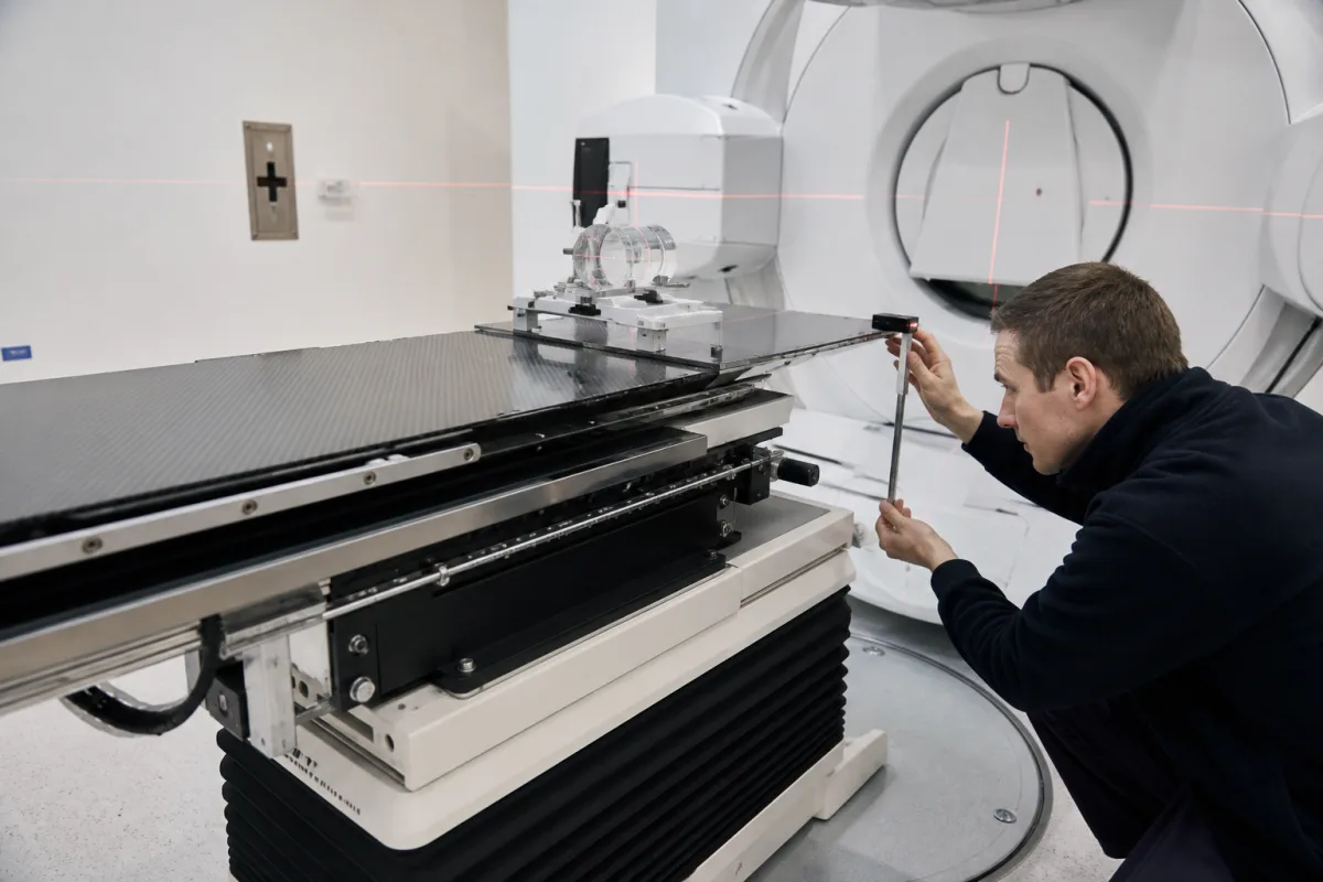
Radiotherapy patient positioning couch: load-bearing tabletop sag, base travel between CT and treatment isocentres, and the extension-plate joint in the beam
The couch base and tabletop that carry the patient into the beam · tabletop sag of 1.5 to 7.3 mm under 135 kg, a 2,106 mm base stroke between CT and treatment isocentres, and 6 MV attenuation of 6.74 % on average and up to 34 % where the extension plate joins the main top
Every millimetre the linac delivers is aimed at a point the couch has to put the patient on. The tabletop bends when a heavy patient lies on it and is pushed out toward the gantry; on a CT-linac the base also has to carry the patient two metres between the scanner and the treatment isocentre and land at the same height; and where an extension plate is clipped to the main top, the joint puts a thicker band of carbon fibre and foam into beams from below. These are load-bearing and structural properties of the couch, separate from how many axes it corrects.
The load-bearing patient support assembly of an external-beam radiotherapy room: couch base, vertical and longitudinal drives, carbon-fibre tabletop and its extension plates, judged by sag under patient load, base travel and repeatability between imaging and treatment isocentres, and attenuation at the tabletop joint. Six-degree-of-freedom couch tops with pitch and roll correction, robotic positioning and insert attenuation are covered on the Six-degree-of-freedom radiotherapy treatment couch page; the accelerator itself, with its beam energies, treatment head, multileaf collimator and commissioning, on the Medical linear accelerator page. Immobilisation masks and vacuum cushions, and couches for diagnostic imaging, are not covered here.
CNFX editorial research · Sources checked October 12, 2026 · 3 sources
How far a loaded tabletop drops: 1.5 mm on a conventional linac couch, 4.1 mm on a CT-linac, 7.3 mm on a CT simulator
Shen and colleagues at the Cancer Hospital of the Chinese Academy of Medical Sciences loaded three couches with 30, 80 and 135 kg spread over 2 m of tabletop and measured the vertical drop at the isocentre at different extensions: [1]
In all three couches the sag grew with load at a fixed extension. [1] The CT-linac couch tested has a 190 kg load capacity, 1,335 mm of tabletop longitudinal travel, ±25 cm lateral and −63 to +17 cm vertical travel, ±3° pitch and roll, and a base that travels 2,106 mm to carry the patient between the CT and treatment centres. Under a 135 kg load its translations were within 0.5 mm of the commanded position, and its pitch and roll readouts differed from an inclinometer at the isocentre by a mean of 0.11° and −0.07°. [1]
Where one patient position serves two isocentres, sag becomes a systematic error. On the same couch the drop between the CT and treatment centres was 1.2 mm unloaded and 3.5 mm at 135 kg; a floor-mounted laser rangefinder that measures the underside of the tabletop corrected it to within 0.6 mm, and over 200 readings in 20 days its angle varied between 42.97° and 43.04°. [1] The authors note that a pitch error of 0.3° moves each end of a 40 cm target by more than 1 mm. Editorial calculation: 200 mm × tan 0.3° ≈ 1.05 mm.
In the United States a powered radiation therapy patient support assembly, defined as an electrically powered adjustable couch intended to support a patient during radiation therapy, is a Class II device under 21 CFR 892.5770. [3]
Ask for sag at the isocentre for your heaviest patient at the longest extension you use, and whether the couch or the imaging system corrects it.
02
The joint where the extension plate meets the main top: 6.74 % mean attenuation against 2.26 % and 1.4 % either side
Kong and colleagues at the Third Affiliated Hospital of Sun Yat-sen University measured 6 MV attenuation on an Elekta Synergy fitted with an iBEAM evo carbon-fibre couch (200 × 53 × 5 cm) and an iBEAM evo Extension 415 plate (41.5 × 53 × 2 cm), both built as a foam core between 1.2 mm carbon-fibre skins, with a 10 × 10 cm field every 10° of gantry rotation. [2]
The authors summarise the main couch and extension plate as about 2.5 % and 1.5 % on average. Attenuation peaked where the beam took its longest path through the couch, near gantry angles of 110° and 250°: up to 34 % measured at the joint and 33 % in the planning system using the actual couch images, against no more than 4.0 % for the planning system's uniform virtual couch model, which assigns relative electron densities of 0.5 to the carbon fibre and 0.03 to the foam. Between −90° and 90° the beam did not pass through the couch and attenuation was close to zero. [2]
For ten nasopharyngeal IMRT plans, pretreatment verification through the joint could fall below an 85 % gamma pass rate at 3 %/3 mm, while beams through the extension plate or main top showed no statistical difference from the reference. [2]
Part of the tabletop in the beam
Mean attenuation, ion-chamber measurement
Mean attenuation, planning system with couch from CBCT
Ask for attenuation data by gantry angle for the tabletop, the extension and the joint between them, and for a couch model that your planning system can import.
03
Base travel of 2,106 mm between CT and treatment isocentres, and how closely it returns
On the CT-linac in the same study the patient is not moved by the tabletop but by the couch base, which runs 2,106 mm between the treatment isocentre and the CT plane; Shen and colleagues loaded it with 140 kg centred on the isocentre and measured the run: [1]
A laser QA device imaged at the head and foot of the tabletop, which the authors set to agree within 2 mm, differed by 0.2 mm horizontally and 1.1 mm vertically unloaded and by 0.3 mm and 1.3 mm under 135 kg. End-to-end tests with a phantom deliberately displaced 15 mm on each axis, at 30, 80 and 140 kg, recovered the shift to within 0.5 mm and 0.5° through both MV cone-beam CT and fan-beam CT workflows. [1]
Editorial note: the 1.2 to 3.5 mm height difference between the two centres in the sag section is of the same order as these travel tolerances, which is why the study treats the rangefinder correction and the base run as one chain. [1]
Check on the couch base
Measured result
Travel from treatment to CT centre against the 2,106 mm preset
For a couch that shuttles between scanner and linac, ask for the base travel accuracy and repeatability under your maximum patient mass, and how height change between the two centres is corrected.
04
What to send when specifying a radiotherapy treatment couch
Paste it into your enquiry below or into an email to a maker, then replace every bracket.
Accelerator and imaging: [make and model; in-room CT or CBCT; distance between isocentres]
Patients: [maximum mass; heaviest treated site; bariatric cases]
Tabletop: [length and width; extension plates; indexing for immobilisation; sag at your extension and load]
Beam: [attenuation by gantry angle for top, extension and joint; planning-system couch model]
Motion: [vertical, longitudinal and lateral travel; base travel and repeatability under load]
Compliance: [regulatory classification in the market of use]
Explore company information and manufacturing capabilities, then discuss the scope of your project with a relevant supplier.
Share this page
Compiled and source-reviewed by the CNFX editorial team.
Each manufacturer above links to the page on that company's own website where the product is listed, with the date we checked it. How we source and review
· Page last updated 13 October 2026
Buyer questions
How much does a radiotherapy couch top sag under a patient?
In one comparison with 135 kg spread over 2 m, the maximum drop at the isocentre was 1.5 mm on a conventional linac couch, 4.1 mm on a CT-linac couch and 7.3 mm on a CT simulator couch. [1]
Why does the joint between couch top and extension plate matter?
For 6 MV on an iBEAM evo couch, mean attenuation was 6.74 % at the joint against 2.26 % through the main top and 1.4 % through the extension, rising to 34 % at the joint near gantry angles of 110° and 250°. [2]
How accurately does a CT-linac couch base return the patient?
In one test with 140 kg, the base ran 2,107 mm against a 2,106 mm preset and repeated its position at each centre within 0.1 mm. [1]
How is a powered treatment couch classified in the US?
As a Class II device under 21 CFR 892.5770, powered radiation therapy patient support assembly. [3]
Sources and what still needs a direct check
Sources checked 2026-10-12. Sag, base travel and motion accuracy come from a mechanical test of three couches at the Cancer Hospital of the Chinese Academy of Medical Sciences; attenuation at the tabletop joint from measurements at Sun Yat-sen University; classification from the US Code of Federal Regulations.