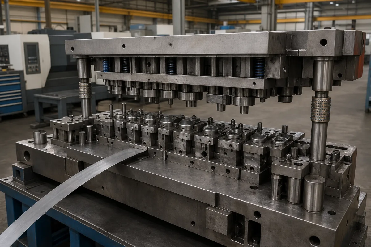
Progressive stamping dies · Strip feed and pitch control by side cut and pilots, punch–die clearance, die life and regrinding, construction, and die marking for the press
A progressive die set punches, cuts and forms a part in a sequence of stations as a metal strip advances one pitch per press stroke, with the finished part cut off at the last station. Settle three things before ordering: the strip layout and how feed pitch will be controlled, the clearances, materials and construction that set part quality and die life, and the press data — tonnage, stroke, shut height and die weight — the die must be marked with and fit.
Progressive and transfer-type stamping dies for sheet metal parts, with their die sets, punches, guides and pilots. Stamping presses, single-station blanking or compound dies sold alone, die-casting dies and extrusion dies are outside this page; stamping presses and extrusion dies have their own pages.
CNFX editorial research · Sources checked October 11, 2026 · 5 sources
MISUMI's press die technology course explains that in cut-and-carry work the material is fed by the feed pitch, and that inaccurate pitch makes the cut shape fluctuate. A side cut stabilises the pitch: the strip edge is notched by the feed pitch and the notched step butts against a stopper. It gives a minimum notch width of about 1.5 to 2 times the material thickness, and warns that a simple L-shaped notch can leave a projection that catches in the material guide and can cause slug (chaff) rising, and shows a more complex notch shape that avoids both problems. [1]
Pilots correct the remaining feed error immediately before cutting. A direct pilot uses a hole in the product itself; an indirect pilot uses a dedicated hole in the scrap, whose position and size can be chosen freely, and the pilot punch enters it right after it is punched. For about 1 mm stock, the course makes the pilot hole diameter about 0.02 mm larger than the pilot punch for high-precision parts and about 0.04 mm for ordinary parts, with a smaller difference for thinner stock; the tip may be bullet- or taper-shaped. [2]
Editorial calculation: for 1.5 mm stock the side-cut notch guideline gives a minimum width of about 2.25 to 3 mm. [1]
Give the die maker the part drawing and annual volume, material grade, thickness and coil width, strip layout preference, feed method (servo feeder, side cut, pilots), press tonnage, stroke, shut height, bolster size and strokes per minute, required part tolerances and burr limit, die construction and steel, sensors, lubrication, tryout and PPAP or sample requirements, and spare punches.
02
Set clearance, die life and marking
The course defines clearance as the gap between punch and die: a larger clearance lowers blanking force but increases shear droop and the slope of the fracture face. It uses a larger clearance as thickness increases, a smaller one for round holes and a larger one for square holes, and warns that too small a clearance on thick or hard material causes secondary shear. [3]
On die life, it says burrs grow fastest in press forming, so maintenance timing can be judged by burr height once an appropriate clearance is set; sharp corners chip and raise burrs sooner. It distinguishes maintenance (regrinding) life from overall life, notes that solid dies thin with each regrind while insert dies regrind only the insert, and that longer life calls for thicker hardened plates and guide bushes. [4]
US OSHA 29 CFR 1910.217 requires all dies to be stamped with their tonnage and stroke requirements (or have them recorded and available to the die setter), with upper die weight where needed for counterbalance adjustment and complete die weight where handling equipment could be overloaded, and requires provision in both upper and lower shoes for securely fastening the die to the press. [5]
03
Strip layout, station list, regrind interval and marking data to ask a die maker for
Ask any die maker for the strip layout, station list, clearance by material, expected regrind interval and the die marking data. [2][5]
04
Side-cut punch, pilots, punches and inserts, plates, shoes and die marking
Feed pitch is held by two parts in turn: the side-cut notch against its stopper, then the pilots that correct the remaining error just before cutting. [1][2]
Shut height, feed pitch, pilot fit, clearance and die weight for a die order
The one numeric guide here is MISUMI's pilot fit of 0.02–0.04 mm on 1 mm stock; die height, stamping speed, operating temperature, maximum strip thickness and lubrication flow are for the die maker to state against your press. [2]
2 companies list this product among what they make. Company figures are quoted from each
company's own website; every card states where the relationship came from.
Kunshan Suliyou Precision Mould Co., Ltd.
Manufacturing site to be confirmed for the order
Its website has a product page for progressive die set.
Product scope checked 2026-10-12
Product page on own website · profile compiled by CNFX from public sources
Explore company information and manufacturing capabilities, then discuss the scope of your project with a relevant supplier.
Share this page
Compiled and source-reviewed by the CNFX editorial team.
Published technical guidance and regulations describe practice and requirements, not a die maker's results. Confirm the legal seller, die maker and tryout results for your order. How we source and review
· Page last updated 13 October 2026
Buyer questions
What is a side cut in a progressive die?
MISUMI describes a notch cut in the strip edge by the feed pitch that butts against a stopper; width about 1.5–2 times thickness. [1]
What is the difference between direct and indirect pilots?
A direct pilot uses a hole in the product; an indirect pilot uses a dedicated hole in the scrap. [2]
How is die maintenance timing judged?
MISUMI says by burr height, once an appropriate clearance is set. [4]
What must be marked on a stamping die?
OSHA 1910.217 requires tonnage and stroke, and upper or total die weight where needed. [5]
Sources and what still needs a direct check
Sources checked 2026-10-11. MISUMI's press die technology course explains side cuts, pilots, clearance and die life; US OSHA 1910.217 sets die marking and fastening requirements.