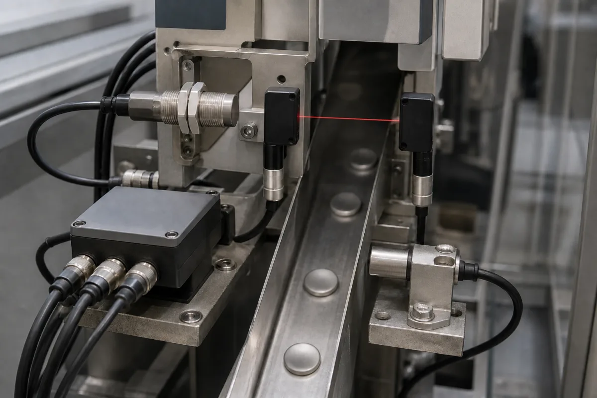
Sensor assembly for a part-counting station: inductive proximity switch and through-beam pair on one mounting set
Counting station built from an inductive switch and a through-beam pair on one bracket set · switching frequency of the slowest sensor, flush or non-flush inductive mounting on a metal track, through-beam pair alignment and test input, M12 wiring and supply current
A sensor assembly in a counting station is a set of sensors pre-mounted on brackets over a feed track or chute: an inductive proximity switch that sees metal parts or carriers, a through-beam photoelectric emitter and receiver facing each other across the track, and the M12 cables, connectors or junction box that bring their signals to the counter or PLC. Because each part has to switch every sensor once, check three things first: the switching frequency of each sensor against the number of parts per second, how the inductive switch is mounted in the metal track and the distance it can be relied on to switch, and how the through-beam pair is aligned and tested.
Multi-sensor assemblies for counting and presence checking on feed tracks, chutes and conveyors: combinations of inductive proximity switches and through-beam photoelectric pairs on shared brackets, their switching frequency, mounting distances, alignment, test inputs, M12 connection and supply current. Single photoelectric sensors and their sensing modes (through-beam, retroreflective, diffuse, background suppression) are covered on the Photoelectric sensor page. Pressure and flow sensor cores, safety light curtains and vision systems are outside this page.
CNFX editorial research · Sources checked October 12, 2026 · 3 sources
400 Hz to 1,500 Hz: the slowest sensor in the assembly sets the parts-per-second limit
The sensors fitted to one counting station switch at different maximum rates. Carlo Gavazzi's EI full-metal M18 inductive switches are rated at ≥500 Hz for the 5 mm flush version and ≥400 Hz for the 8 mm non-flush version, with its M8 types at ≥2,000 Hz and 15 mm M30 types at ≥100 Hz. [1] Festo's SOIA-M18 IO-Link inductive sensor lists a maximum switching frequency of 1,200 Hz [2], and SICK's W12 through-beam pair a switching frequency of 1,500 Hz with a response time of ≤330 µs. [3]
Editorial calculation: one passing part switches each sensor on and off once, so an assembly combining the 1,500 Hz SICK pair with an 8 mm Gavazzi M18 non-flush switch cannot be relied on above 400 parts per second, the lower of the two ratings, before any allowance for gaps between parts. [3][1]
Both IO-Link sensors also report over the IO-Link link, but at a slower cycle: Festo gives a minimum IO-Link cycle time of 3.2 ms and SICK a cycle time of 2.3 ms. [2][3] Editorial calculation: 1 ÷ 3.2 ms ≈ 312 and 1 ÷ 2.3 ms ≈ 435 process-data updates per second, below the 1,200 and 1,500 Hz switching ratings, so a counter wired to the switching output sees more events per second than one reading IO-Link process data.
SICK's W12 slows when its built-in logic is used: with Smart Task logic in SIO mode the switching frequency is listed at 1,300 Hz and the response time at 390 µs, and in IO-Link mode at 1,200 Hz and 420 µs. [3]
Give the supplier the parts per second at peak, the length and gap of the parts as they pass, the material (metal or not), and whether the counter reads the switching output or IO-Link data.
02
Flush or non-flush in a metal track: rated, assured and usable switching distance
Carlo Gavazzi's M18 inductive switch has a rated operating distance (Sn) of 5 mm when built for flush mounting in metal and 8 mm for non-flush mounting. Its datasheet defines the assured operating distance as 0 ≤ Sa ≤ 0.81 × Sn, the effective operating distance as 0.9 to 1.1 × Sn and the usable distance as 0.9 to 1.1 × Sr, with hysteresis of 1 to 15% of the sensing distance and repeat accuracy ≤5%. [1]
Editorial calculation: 0.81 × 5 mm = 4.05 mm assured distance for the flush M18 and 0.81 × 8 mm = 6.48 mm for the non-flush M18; the gap between the sensor face and the part's path on the track should stay inside that figure, not the rated distance. [1]
Festo's SOIA-M18 is a flush-mounting, PBT-housed sensor with a 0 to 8 mm operating and measuring range, a factory setting of 6.8 mm for switching point SSC1 and 4.0 mm for SSC2, 0.01 mm resolution and ±0.08 mm repetition accuracy. Its datasheet gives a tightening torque of 0 to 30 Nm and IP65 and IP67 protection. [2] Editorial note: an analogue-distance sensor of this kind can have its switching point taught to the track after mounting, while a fixed switch is placed by shims or thread position.
03
Through-beam pair across the track: light spot, alignment aid and the sender-off test input
SICK's W12 through-beam pair (sender WSO12F, receiver WEO12F) has a 30 m maximum range with 0 to 20 m recommended, a visible red 635 nm LED, a rectangular light spot of 100 × 70 mm at 5 m and a squint angle within ±1.5°. A blue BluePilot LED serves as an alignment aid and a yellow LED shows the received-beam status. [3]
Pin 4 of the W12 sender is an input that switches the sender off (LOW active), and the receiver has two complementary push-pull PNP/NPN outputs with light or dark switching. [3] Editorial note: a sender-off input lets the PLC turn the beam off and check that the receiver output changes, a way of proving the pair is working before a count starts.
Each sensor in the assembly draws supply current: ≤25 mA for the W12 sender and ≤20 mA for its receiver at 24 V without load, 17 mA no-load for Festo's SOIA-M18, and ≤7 mA for Gavazzi's M18. [3][2][1] Editorial calculation: a station with one W12 pair and one Festo M18 draws about 25 + 20 + 17 = 62 mA before output loads, to be added to the outputs' load current (up to 100 mA per output on both the SICK and Festo parts) when sizing the supply or junction box.
All three connect through M12 male connectors: 4-pin on the W12, 3-core A-coded to EN 61076-2-101 on the Festo M18, and M12 plugs on Gavazzi's M12, M18 and M30 types. The W12 housing is zinc diecast, 15.6 × 49.5 × 43.1 mm, rated IP66, IP67 and IP69. [3][2][1]
04
Send the track, parts and counting data together
Paste it into your enquiry below or into an email to a maker, then replace every bracket.
Parts: [material; size; length and gap on the track; parts per second at peak]
Track: [metal or plastic; distance from sensor face to part path; width across for the beam]
Sensors: [inductive size and flush/non-flush; through-beam range; PNP/NPN; light or dark switching]
Counter: [switching output or IO-Link; PLC input type]
Wiring: [M12 3- or 4-pin; cable length; junction box]
Environment: [IP rating; temperature; coolant or cleaning agents]
Explore company information and manufacturing capabilities, then discuss the scope of your project with a relevant supplier.
Share this page
Compiled and source-reviewed by the CNFX editorial team.
Each manufacturer above links to the page on that company's own website where the product is listed, with the date we checked it. How we source and review
· Page last updated 13 October 2026
Buyer questions
What limits how fast a sensor assembly can count?
The lowest switching frequency among its sensors; in the sources reviewed this ranges from ≥400 Hz for an 8 mm non-flush M18 inductive switch to 1,500 Hz for a W12 through-beam pair. [1][3]
How close must the part pass an M18 inductive switch?
Within its assured operating distance, 0.81 × Sn per Carlo Gavazzi; about 4.05 mm for a 5 mm flush M18 and 6.48 mm for an 8 mm non-flush M18. [1]
How can a through-beam pair be tested before counting?
SICK's W12 sender has an input on pin 4 that switches the sender off, so the receiver output can be checked to change. [3]
Is IO-Link fast enough for counting?
Festo gives a 3.2 ms minimum IO-Link cycle and SICK 2.3 ms, slower than their 1,200 and 1,500 Hz switching outputs. [2][3]
Sources and what still needs a direct check
Sources checked 2026-10-12. Figures come from the makers' datasheets for single part numbers: Carlo Gavazzi's EI series datasheet dates from 1999 and Festo's and SICK's from 2026. Ratings for other sensors differ.