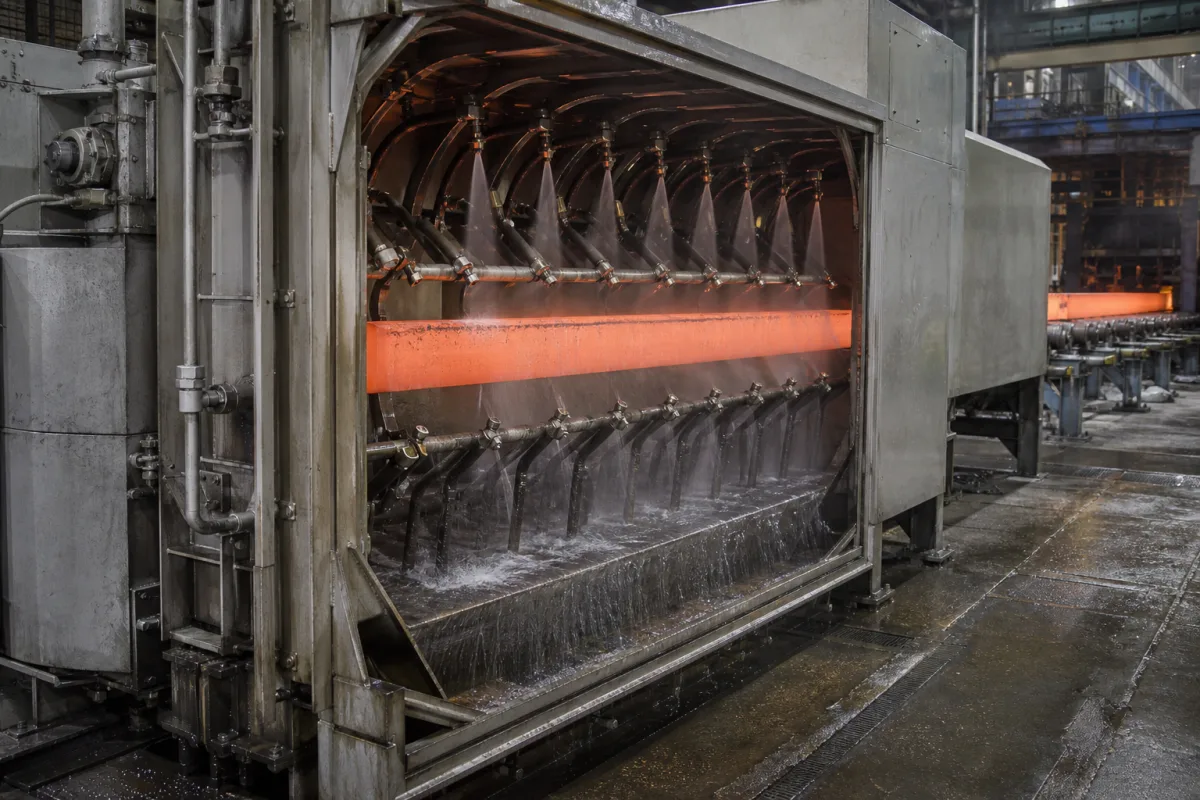
Secondary-cooling spray chamber structure and foot-roller support for continuous casters
Caster secondary-cooling chamber structure · foot-roller hanger under the mould, roller lines and strand support, chamber length and heat, drained water and discharge limits
The spray chamber structure of a continuous caster is the steel frame and enclosure below the mould that holds the strand-support rolls and the spray pipework around the hot strand, keeps water and steam inside and drains the water away. Its first part, the foot-roller unit hung from the mould, carries the thin shell just after it leaves the mould. Ask three things first: how the foot-roller hanger and roll lines support the strand, how long and how heat-exposed the chamber is, and how much water it must collect and send to treatment.
The structural side of continuous-caster secondary cooling for billets and blooms: foot-roller hangers and roll frames under the mould, chamber frames, enclosure panels and doors, and the drainage that takes spray water to treatment. Spray nozzles, headers, cooling loops and their water and air supply are covered on the Secondary cooling (spray) zone page; complete billet casters, their section, speed, strand count and plant scope on the Billet continuous caster page. Moulds, withdrawal and straightening units, cut-off machines and laboratory salt-spray or rain-test chambers are outside this page.
CNFX editorial research · Sources checked October 12, 2026 · 3 sources
Support the strand under the mould with the foot-roller hanger
Androsenko and co-authors at Nosov Magnitogorsk State Technical University describe the foot-roller unit of a billet caster's secondary cooling zone: a base attached to the bottom plate of the mould, angle-section support brackets with two rows of holes for roller assemblies on axes and plain bearings, brackets set to the caster's basic radius, and the cooling nozzles attached to the base with water supplied between the rollers. Rollers in contact with hot metal take cyclic thermal stresses and mechanical load from the ferrostatic pressure of liquid steel, leading to wear, cracking and sometimes breakage. [1]
They report breakouts between the mould and the foot-roller unit and name roller spacing (mould to first line, first to second line, second line to the first bending roll) among the main design causes. Replacing two roller lines with three on the same base and brackets reduced calculated total deformation of billet and hanger by 30% and equivalent stress by 38%: von Mises stress fell from 8.5062 MPa to 5.2872 MPa and billet deformation from 2.5277 µm to 1.792 µm. The rebuilt hanger had its roller necks clad by a friction method to resist wear. [1]
The same paper notes that roller diameters grow in downstream sections as the shell thickens, that frames with foot rollers on all four sides are used against bulging along the slab edges, and that water consumption when casting killed steel is 0.4 to 1.0 m³/t at withdrawal speeds of 1.0–1.4 m/min. [1]
Editorial note: ask the supplier for the roll pitch from the mould exit through the first lines, the roll diameter and bearing type, and the stress check of the hanger, not only the frame drawing.
Send the cast sections and casting speed range, caster radius, mould type and bottom-plate interface, number of foot-roller lines and roll pitch, roll diameter and bearing type, chamber length and number of zones, enclosure material and panel thickness, access doors, steam exhaust and drain connections, and the plant's discharge limits.
02
Size the chamber for each zone's flow, pressure and heat
Marius and Erika Ardelean of the Hunedoara Faculty of Engineering describe the secondary area as spraying water under pressure that penetrates the steam layer on the strand, taking the surface from 1,200–1,300 °C at the mould exit to 700–900 °C at the end of the secondary area. They give, as a general figure, that the secondary area covers over 30 up to 50% of the liquid core length and is divided into individually controlled sub-areas. [2]
Their plant measurements show the water the chamber must drain: on 240 × 270 mm blooms at 8.6–10.7 bar the three areas took up to 81, 100 and 112 l/min; on Ø150 mm rounds at 8.2–8.6 bar up to 60, 84 and 73 l/min. [2] Editorial calculation: the bloom maximum is 81 + 100 + 112 = 293 l/min, about 17.6 m³/h per strand.
Editorial calculation, cross-checking with the Magnitogorsk range and assuming a steel density of 7.8 t/m³: a Ø150 mm strand at 1.2 m/min carries about 0.0177 m² × 1.2 m/min × 7.8 t/m³ ≈ 0.165 t/min, so 0.4–1.0 m³/t corresponds to roughly 66–165 l/min, the same order as the 41–84 l/min per area measured at Hunedoara. [1][2]
03
Mount the nozzles on the frame for each zone
In the foot-roller unit described from Magnitogorsk, the cooling nozzles are attached to the same base that carries the roller brackets, and the water is supplied between the rollers; the brackets themselves are set to the caster's basic radius. [1] The Hunedoara authors note that nozzle spray angle, the distances between nozzles and the water pressure are regulated so that a steady or almost steady temperature is kept around the strand periphery, with water or a water-air mixture as the coolant. [2]
Editorial note: on the chamber structure this means nozzle mountings that follow the caster radius between roll lines and can be adjusted for angle and distance; ask for a drawing of nozzle positions relative to the rolls for the smallest and largest section, and for how a nozzle is changed without dismantling the roll frame. Nozzle types, sizes and turndown belong to the spray-zone specification rather than the structure.
04
Plan for the water that leaves the chamber
Under 40 CFR 420 subpart F, which applies to discharges from the continuous casting of molten steel through water-cooled moulds, US EPA's BPT limits are 0.0780 kg of TSS and 0.0234 kg of oil and grease per 1,000 kg of product as a daily maximum, 0.0260 and 0.0078 kg as 30-day averages, with pH 6.0–9.0. BAT limits for lead are 0.0000939 kg and for zinc 0.000141 kg per 1,000 kg as daily maxima. [3]
Editorial calculation: for a caster producing 1,000 t a day, the BPT daily maximum allows 78 kg of TSS and 23.4 kg of oil and grease in the discharge. Chamber drains and the downstream scale pit and filters are therefore part of the order boundary even when the chamber itself is bought as a structure.
05
What the chamber frame has to carry and hold
The structure items below follow from the foot-roller, chamber and water data above; values are cited where a source gives them.
Item
Why it matters
Fix in the order
Foot-roller hanger
Base on the mould bottom plate; brackets set to caster radius. [1]
Roll lines, pitch, bearings.
Roll frames downstream
Roll diameter grows downstream; four-sided frames against edge bulging. [1]
Roll sizes and frame layout.
Enclosure panels
Hot strand at 1,200–1,300 °C entering the chamber. [2]
Material, wall thickness, access doors.
Chamber length
Over 30 up to 50% of liquid core length, as a general figure. [2]
Explore company information and manufacturing capabilities, then discuss the scope of your project with a relevant supplier.
Share this page
Compiled and source-reviewed by the CNFX editorial team.
Each manufacturer above links to the page on that company's own website where the product is listed, with the date we checked it. How we source and review
· Page last updated 13 October 2026
Buyer questions
Why add a third line of foot rollers under the mould?
In the Magnitogorsk study, three lines instead of two cut calculated billet and hanger deformation by 30% and equivalent stress by 38%. [1]
How long is the secondary-cooling chamber?
The Hunedoara authors give, as a general figure, over 30 up to 50% of the liquid core length. [2]
Is caster spray water regulated when discharged?
Yes. 40 CFR 420 subpart F sets BPT limits of 0.0780 kg TSS per 1,000 kg of product as a daily maximum. [3]
Sources and what still needs a direct check
Sources checked 2026-10-12. The Magnitogorsk paper analyses and rebuilds a billet caster's foot-roller hanger; the Hunedoara paper reports plant measurements of secondary-area water on a bloom and billet caster; the EPA regulation sets discharge limits for continuous casting.