Editorial Technical Reference

Secondary Cooling System

This page explains how Secondary Cooling System is classified within Basic Metal Manufacturing. Technical values and manufacturer relationships are research references; confirm the current specification and supplier evidence for each order.

Technical Definition & Core Assembly

A cooling system that controls the solidification rate of non-ferrous metal billets after initial solidification in continuous casting.

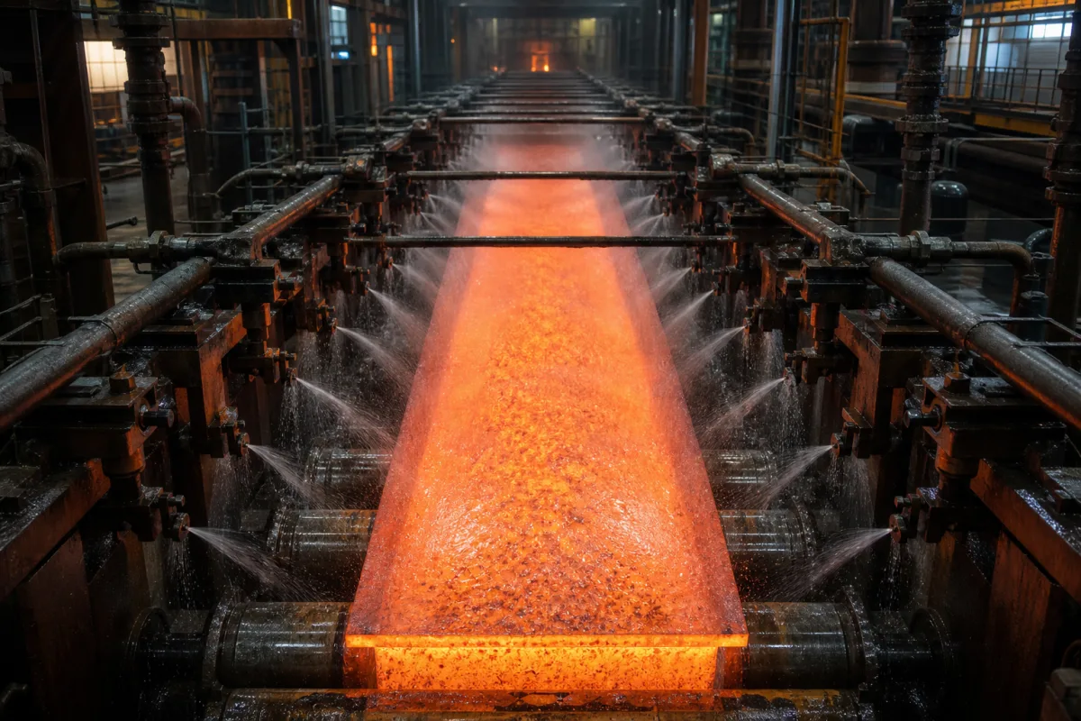
Representative product image. Confirm appearance and specifications with the manufacturer.

Product Specifications

Technical details and manufacturing context for Secondary Cooling System

Definition
The Secondary Cooling System is a critical component of a Continuous Casting Machine for Non-Ferrous Metals. It is responsible for the controlled cooling of the metal strand after it exits the mold (primary cooling zone). This system manages the heat extraction rate to ensure proper solidification structure, prevent surface defects like cracks, and achieve the desired metallurgical properties in the final cast product. It typically operates on the solidified shell of the billet, bloom, or slab. The system consists of multiple cooling zones (sprays or chambers) arranged along the casting strand's path. A coolant (typically water, water-air mist, or a specialized fluid) is precisely sprayed onto the metal surface. The flow rate, pressure, spray pattern, and temperature of the coolant in each zone are automatically controlled based on casting speed, alloy type, and desired thermal profile. This extracts heat uniformly to complete solidification and control the temperature gradient, minimizing thermal stress. The system is designed for non-ferrous metals and includes components such as stainless steel nozzles and headers, carbon steel piping and framework, copper alloy spray nozzles, and polymer/composite spray headers and seals. Key parameters include cooling water flow rate (80–200 m³/h), water pressure (0.4–0.8 MPa), spray nozzle quantity (120–240 pcs), cooling zone length (3–6 m), billet temperature range (800–1100 °C), water temperature (20–35 °C), control accuracy (±2%), response time (≤1 s), electrical supply (380–480 V AC, IEC 60038), power consumption (15–45 kW), ingress protection (IP54–IP65, IEC 60529), noise level (≤85 dB(A), ISO 3744), weight (1500–3000 kg), and material grade (304/316, ASTM A240). These values are reference ranges and must be verified for the specific model and application. Always confirm model-specific values and standards with the legal manufacturer or supplier.
Working Principle
The system operates by spraying coolant onto the moving strand in multiple zones. Each zone has individually controlled flow rate, pressure, and spray pattern, adjusted automatically based on casting speed and alloy. The coolant extracts heat uniformly, completing solidification and controlling the temperature gradient to minimize thermal stress. The control system uses sensors and actuators to maintain precise cooling, with response time ≤1 s and control accuracy ±2%.
Common Materials
Stainless Steel (Nozzles, Headers), Carbon Steel (Piping, Framework), Copper Alloys (Spray Nozzles), Polymer/Composite (Spray Headers, Seals)
Technical Parameters
ParameterTypical rangeNotes & selection driver
Cooling Water Flow Rate80–200 m³/hDetermines cooling intensity and billet surface temperature.
Water Pressure0.4–0.8 MPaAffects spray atomization and cooling uniformity.
Spray Nozzle Quantity120–240 pcsMore nozzles improve cooling uniformity.
Cooling Zone Length3–6 mLonger zones allow gradual cooling.
Billet Temperature Range800–1100 °CTypical surface temperature after secondary cooling.
Water Temperature20–35 °CHigher temperatures reduce cooling efficiency.
Control Accuracy±2 %Precision of flow control for consistent cooling.
Response Time≤1 sFast response to changes in casting speed.
Electrical Supply380–480 V ACThree-phase, 50/60 Hz.IEC 60038
Power Consumption15–45 kWIncludes pumps and control system.
Ingress ProtectionIP54–IP65Protection against water and dust.IEC 60529
Noise Level≤85 dB(A)At 1 m distance.ISO 3744
Weight1500–3000 kgDepends on configuration and materials.
Material Grade304/316Stainless steel for corrosion resistance.ASTM A240

Ranges are indicative industry figures for RFQ preparation, not a supplier commitment. Confirm every value and standard with the legal manufacturer before ordering.

Components / BOM
  • Spray Nozzle Array
    Distributes coolant uniformly over the metal strand surface in a specific pattern (flat fan, full cone).
    Material: Stainless Steel, Copper Alloy
  • Cooling Water Header/Piping
    Manifold system that supplies coolant from the main pump to the individual spray zones and nozzles.
    Material: Carbon Steel, Stainless Steel
  • Flow Control Valves
    Regulates the flow rate and pressure of coolant to each spray zone, often automated via PLC.
    Material: Stainless Steel, Brass
  • Spray Chamber/Support Structure
    Encloses the spray area, contains splashing, and provides structural support for nozzles and piping.
    Material: Carbon Steel (frame), Stainless Steel (liners)
  • Control System and Sensors
    Reads strand temperature and casting speed and sets each zone's water flow.

Industrial Ecosystem & Supply Chain Structure

Complementary Systems
Downstream Applications
Specialized Tooling

Application Fit & Sizing Matrix

Operational Limits
pressure: Up to 10 bar (system operating pressure)
flow rate: 50-500 m³/h (coolant circulation capacity)
temperature: 20-80°C (coolant temperature range)
slurry concentration: Up to 15% solids by weight (for slurry-based systems)
Media Compatibility
✓ Aluminum alloys ✓ Copper alloys ✓ Zinc alloys
Unsuitable: Ferrous metals (steel/iron) - requires different cooling parameters
Sizing Data Required
  • Billet cross-sectional dimensions (mm)
  • Casting speed (m/min)
  • Required cooling intensity (kW/m²)

Reliability & Engineering Risk Analysis

Failure Mode & Root Cause
Corrosion-induced leakage
Cause: Chemical attack from coolant additives, dissolved oxygen, or pH imbalance leading to pitting and perforation of pipes and heat exchangers
Pump impeller cavitation
Cause: Insufficient net positive suction head (NPSH) due to clogged filters, low reservoir levels, or excessive pump speed causing vapor bubble formation and collapse
Maintenance Indicators
  • Unusual gurgling or hammering sounds in piping indicating air entrainment or cavitation
  • Visible rust-colored deposits or weeping at pipe joints and heat exchanger surfaces
Engineering Tips
  • Implement real-time water chemistry monitoring with automated dosing to maintain pH (8.5-9.5) and corrosion inhibitor concentrations
  • Install duplex filtration systems with differential pressure monitoring and scheduled rotation to prevent particulate-induced wear

Indicative industry ranges for design and RFQ preparation. Confirm the exact figures and applicable standard with the manufacturer before specifying.

Compliance & Manufacturing Standards

Applicable Standards
ISO 1217:2009 (Displacement compressors - Acceptance tests) ANSI/ASHRAE 15:2022 (Safety Standard for Refrigeration Systems) DIN EN 378:2017 (Refrigerating systems and heat pumps - Safety and environmental requirements)

Quoted from the published standard.

Manufacturing Precision
  • Coolant flow rate: +/-5% of design specification
  • Temperature control accuracy: +/-1.5°C across all cooling zones
Quality Inspection
  • Pressure decay leak test (per ISO 20486)
  • Coolant chemical composition analysis (ASTM D1122 for glycol concentration)

Manufacturers of Secondary Cooling System

Manufacturer profiles associated with Secondary Cooling System.

Sourcing Secondary Cooling System from China?
Tell us your specification and target quantity — we will match it against manufacturer records and come back with the factories that fit.
Request manufacturers We manufacture this

Manufacturer listings support early research and capability understanding. They are not certification, ranking, or transaction guarantees.

Technical documentation
Request current drawings, revision history, and a signed specification sheet.
Manufacturing capability
Verify equipment lists, process limits, capacity, and representative production evidence.
Inspection readiness
Confirm test methods, calibrated equipment, sampling plans, and traceable reports.
Supplier transparency
Check the legal entity, factory address, ownership, certifications, and direct contacts.

CNFX does not score or rank suppliers. Buyers must verify all claims and documents with the legal manufacturer before ordering.

Supply Chain Compatible Machinery & Devices

Continuous Casting Machine

Industrial machine for solidifying molten metal into continuous billets/blooms/slabs.

Explore Specs →
Vacuum Induction Melting Furnace

Industrial furnace for melting metals under vacuum using electromagnetic induction

Explore Specs →
Electroslag Remelting Furnace

An industrial furnace used in basic metal manufacturing for secondary refining of alloys through the electroslag remelting (ESR) process.

Explore Specs →
Molten Metal Temperature Measurement System

Automated system for continuous temperature monitoring of molten metals during processing.

Explore Specs →

Frequently Asked Questions

What is the primary function of the secondary cooling system?

It controls the cooling rate of the metal strand after it leaves the mold, ensuring proper solidification and preventing defects.

What are typical operating parameters?

Water flow rate 80–200 m³/h, pressure 0.4–0.8 MPa, nozzle count 120–240, zone length 3–6 m, and billet temperature 800–1100 °C. These are reference ranges; confirm for your model.

Which materials are used in construction?

Stainless steel for nozzles and headers, carbon steel for piping and framework, copper alloys for spray nozzles, and polymer/composite for headers and seals.

What standards apply?

Electrical supply per IEC 60038, ingress protection per IEC 60529, noise per ISO 3744, and material grade per ASTM A240. Verify compliance with the manufacturer.

Data Basis

Editorial classification, named public sources where available, and source-reviewed manufacturer records.

Preliminary Technical Classification
This page supports structured research, RFQ preparation, and supplier evaluation. It does not replace buyer-led supplier qualification, standards review, or technical approval.
Buyer enquiry

Request manufacturing insight for Secondary Cooling System

Ask for use case, specification boundaries, supplier type, and RFQ preparation information for this product.

Where it goes
Straight to the CNFX editorial desk, and to the manufacturer if this product is linked to a claimed profile. Nothing is broadcast to a supplier list.
Your details stay here
We do not sell or rent enquiry data, and we do not add you to a mailing list. Used only to answer this request.
No commission, no middleman
CNFX is a directory. We take no cut of any order and never negotiate on a supplier's behalf.
What we don't claim
A listing is not an endorsement. Qualify every supplier and verify every figure yourself before ordering.

Your business information is used only to process this request.

Thank you! Your message has been sent. We'll respond within 1–3 business days.
Sorry, we couldn't send your message. Please try again, or email us at contact@cnfx.com.

Need to Manufacture Secondary Cooling System?

Compare manufacturer profiles with relevant product and process capability.

Previous Product
Screwdown Mechanism
Next Product
Servo Valve
Get QuotesChat