Editorial Technical Reference

Structural Frame (Gantry)

This page explains how Structural Frame (Gantry) is classified within Machinery and Equipment Manufacturing. Technical values and manufacturer relationships are research references; confirm the current specification and supplier evidence for each order.

Technical Definition & Core Assembly

The rigid supporting structure that forms the main framework of an XY motion system's gantry assembly.
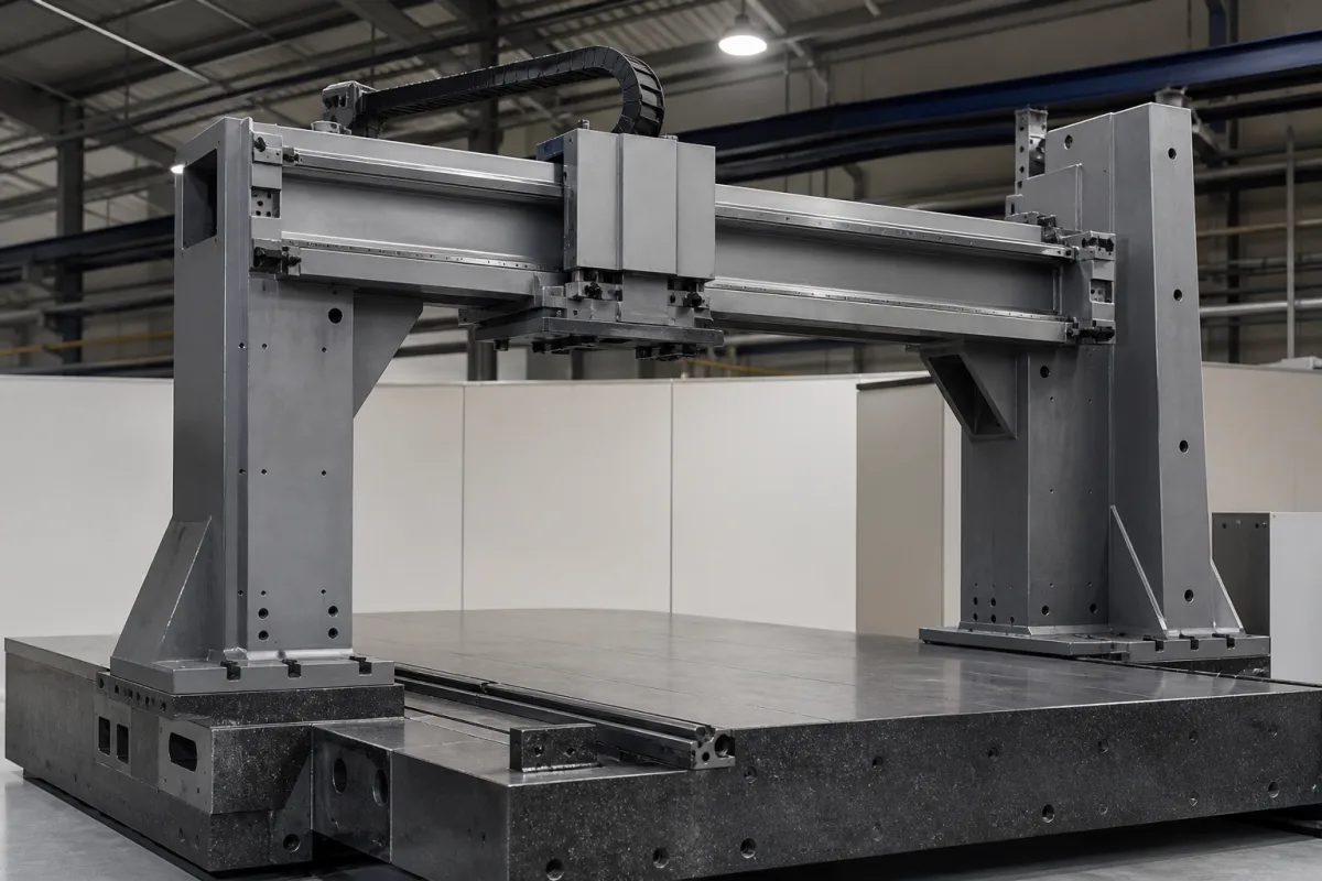
Representative product image. Confirm appearance and specifications with the manufacturer.

Product Specifications

Technical details and manufacturing context for Structural Frame (Gantry)

Definition
The structural frame, commonly referred to as the gantry, is the foundational component of an XY motion system. It provides the rigid, stable platform upon which the X-axis and Y-axis linear motion components (such as rails, carriages, and drives) are mounted. Its primary role is to maintain precise geometric alignment and resist deflection under operational loads, ensuring the overall accuracy and repeatability of the system's positioning. The frame is designed with a high stiffness-to-weight ratio to minimize deformation from the combined weight of mounted components (motors, carriages, end-effectors) and dynamic forces generated during acceleration and deceleration. Its geometry and material properties determine the system's resonant frequencies and its ability to dampen vibrations, directly impacting positioning stability. Typical materials include aluminum alloy (e.g., 6061-T6), steel (e.g., A36 or stainless steel), and carbon fiber composite. Key parameters to verify for a specific application include frame width (800–2000 mm), frame height (500–1500 mm), load capacity (500–5000 kg), positioning accuracy (±0.02–±0.05 mm per ISO 230-2), repeatability (±0.01–±0.02 mm per ISO 230-2), straightness (0.02–0.05 mm/m per ISO 230-1), operating temperature (0–50 °C), ingress protection (IP54–IP65 per IEC 60529), material grade (Q235–Q345 per GB/T 700), and frame weight (500–3000 kg). These values are reference ranges; the actual model must be confirmed with the manufacturer. The frame's performance is critical for precision machining, and its selection depends on the required travel, load, and accuracy. Verification questions include checking the frame's flatness, parallelism, and rigidity under load. Maintenance signals include visible cracks, excessive vibration, or loss of positioning accuracy. Failure boundaries are exceeded when deflection or thermal expansion causes the system to fall out of specified tolerances. Always verify model-specific values and standards with the legal manufacturer or supplier.
Working Principle
The frame functions as a static, load-bearing structure. It is designed with high stiffness-to-weight ratio to minimize deformation from the combined weight of mounted components (motors, carriages, end-effectors) and dynamic forces generated during acceleration/deceleration. Its geometry and material properties determine the system's resonant frequencies and its ability to dampen vibrations, directly impacting positioning stability.
Common Materials
Aluminum Alloy (e.g., 6061-T6), Steel (e.g., A36 or Stainless Steel), Carbon Fiber Composite
Technical Parameters
ParameterTypical rangeNotes & selection driver
Frame Width800–2000 mmDetermines the maximum X-axis travel.
Frame Height500–1500 mmAffects Z-axis clearance and stiffness.
Load Capacity500–5000 kgMaximum static load on the gantry.
Positioning Accuracy±0.02–±0.05 mmCritical for precision machining.ISO 230-2
Repeatability±0.01–±0.02 mmEnsures consistent positioning over cycles.ISO 230-2
Straightness0.02–0.05 mm/mAffects motion quality along the axis.ISO 230-1
Operating Temperature0–50 °COutside this range, thermal expansion affects accuracy.
Ingress ProtectionIP54–IP65Protects against dust and water jets.IEC 60529
Material GradeQ235–Q345Higher grade for higher strength and stiffness.GB/T 700
Frame Weight500–3000 kgAffects foundation requirements and shipping cost.

Ranges are indicative industry figures for RFQ preparation, not a supplier commitment. Confirm every value and standard with the legal manufacturer before ordering.

Components / BOM
  • Base Beam / Bed Part
    Forms the stationary foundation, typically supporting the X-axis linear guides.
    Material: steel or aluminum
  • Vertical Columns / Legs Part
    Provide vertical support for the cross-beam, transferring loads to the base.
    Material: steel or aluminum
  • Cross-Beam / Bridge
    The horizontal member that moves along the X-axis, carrying the Y-axis motion components and end-effector.
    Material: aluminum or carbon fiber composite
  • Reinforcement Ribs / Gussets Part
    Internal or external structural elements added to increase stiffness and reduce deflection at critical joints.
    Material: same as main frame material

Applied To / Applications

This component is essential for the following industrial systems and equipment:

Industrial Ecosystem & Supply Chain Structure

Complementary Systems
Downstream Applications
Specialized Tooling

Application Fit & Sizing Matrix

Operational Limits
pressure: Not applicable (structural component)
other spec: Max dynamic load: 5000 N, Max static load: 7500 N, Vibration tolerance: ≤5 g RMS, Deflection limit: ≤0.1 mm/m under max load
temperature: -20°C to +80°C (operational), -40°C to +100°C (storage)
Media Compatibility
✓ Cleanroom environments (ISO Class 5-8) ✓ Industrial automation cells ✓ Precision measurement systems
Unsuitable: Corrosive chemical exposure (acids, strong solvents)
Sizing Data Required
  • Maximum payload mass (kg)
  • Required travel distance in X and Y axes (mm)
  • Required positioning accuracy/repeatability (μm)

Reliability & Engineering Risk Analysis

Failure Mode & Root Cause
Fatigue cracking
Cause: Cyclic loading from operational vibrations, material stress concentrations at weld joints or sharp corners, and inadequate design for dynamic loads leading to crack initiation and propagation.
Corrosion-induced weakening
Cause: Exposure to moisture, chemicals, or harsh environmental conditions without proper protective coatings, leading to material degradation, loss of structural integrity, and potential collapse.
Maintenance Indicators
  • Visible cracks or deformation in structural members, especially at welds or connection points
  • Unusual vibrations, creaking noises, or shifting during operation indicating instability
Engineering Tips
  • Implement regular non-destructive testing (NDT) such as ultrasonic or magnetic particle inspection to detect early-stage fatigue cracks before they propagate
  • Apply and maintain protective coatings (e.g., galvanization, epoxy paints) and ensure proper drainage to prevent water accumulation and corrosion hotspots

Indicative industry ranges for design and RFQ preparation. Confirm the exact figures and applicable standard with the manufacturer before specifying.

Compliance & Manufacturing Standards

Applicable Standards
ISO 230-1:2012 - Test code for machine tools - Part 1: Geometric accuracy of machines operating under no-load or quasi-static conditions ANSI B11.19-2019 - Performance Requirements for Safeguarding DIN 5510-2:2009-05 - Preventive fire protection in railway vehicles; Part 2: Fire behaviour and fire side effects of materials and parts; Classification, requirements and test methods

Quoted from the published standard.

Manufacturing Precision
  • Flatness of mounting surfaces: +/- 0.1 mm per meter
  • Squareness of vertical columns to base: 0.05 mm per 300 mm
Quality Inspection
  • Dimensional Verification with Laser Tracker
  • Magnetic Particle Inspection for weld integrity

Manufacturers of Structural Frame (Gantry)

Manufacturer profiles associated with Structural Frame (Gantry).

Sourcing Structural Frame (Gantry) from China?
Tell us your specification and target quantity — we will match it against manufacturer records and come back with the factories that fit.
Request manufacturers We manufacture this

Manufacturer listings support early research and capability understanding. They are not certification, ranking, or transaction guarantees.

Technical documentation
Request current drawings, revision history, and a signed specification sheet.
Manufacturing capability
Verify equipment lists, process limits, capacity, and representative production evidence.
Inspection readiness
Confirm test methods, calibrated equipment, sampling plans, and traceable reports.
Supplier transparency
Check the legal entity, factory address, ownership, certifications, and direct contacts.

CNFX does not score or rank suppliers. Buyers must verify all claims and documents with the legal manufacturer before ordering.

Supply Chain Compatible Machinery & Devices

Automated Powder Coating System

Integrated industrial system for applying dry powder coatings to metal substrates.

Explore Specs →
Centrifugal Pump Impeller

The centrifugal pump impeller is a critical rotating component that converts mechanical energy from the motor into kinetic energy in fluid systems.

Explore Specs →
High-Precision CNC Laser Cutting Machine

Computer-controlled industrial machine using focused laser beams to cut sheet metal with micron-level accuracy.

Explore Specs →
Industrial-Grade Hydraulic Cylinder Piston Rod

This industrial-grade piston rod is a precision-ground cylindrical component designed for use in hydraulic cylinders.

Explore Specs →

Frequently Asked Questions

What materials are commonly used for the gantry frame?

Common materials include aluminum alloy (e.g., 6061-T6), steel (e.g., A36 or stainless steel), and carbon fiber composite. The choice affects stiffness, weight, and damping.

How do I verify the positioning accuracy of the frame?

Positioning accuracy is specified as ±0.02–±0.05 mm per ISO 230-2. You must confirm the actual value for your specific model with the manufacturer, as it depends on the frame's geometry and assembly.

What is the load capacity range for such frames?

The load capacity is typically 500–5000 kg, but this is a reference range. The actual capacity depends on the frame's design and materials; always check the manufacturer's specifications.

What standards apply to the frame's straightness and repeatability?

Straightness is referenced to ISO 230-1 (0.02–0.05 mm/m), and repeatability to ISO 230-2 (±0.01–±0.02 mm). These standards are for verification; compliance must be confirmed with the supplier.

Data Basis

Editorial classification, named public sources where available, and source-reviewed manufacturer records.

Preliminary Technical Classification
This page supports structured research, RFQ preparation, and supplier evaluation. It does not replace buyer-led supplier qualification, standards review, or technical approval.
Buyer enquiry

Request manufacturing insight for Structural Frame (Gantry)

Ask for use case, specification boundaries, supplier type, and RFQ preparation information for this product.

Where it goes
Straight to the CNFX editorial desk, and to the manufacturer if this product is linked to a claimed profile. Nothing is broadcast to a supplier list.
Your details stay here
We do not sell or rent enquiry data, and we do not add you to a mailing list. Used only to answer this request.
No commission, no middleman
CNFX is a directory. We take no cut of any order and never negotiate on a supplier's behalf.
What we don't claim
A listing is not an endorsement. Qualify every supplier and verify every figure yourself before ordering.

Your business information is used only to process this request.

Thank you! Your message has been sent. We'll respond within 1–3 business days.
Sorry, we couldn't send your message. Please try again, or email us at contact@cnfx.com.

Need to Manufacture Structural Frame (Gantry)?

Compare manufacturer profiles with relevant product and process capability.

Previous Product
Straightening Roll
Next Product
Suction and Discharge Manifolds
Get QuotesChat