Editorial Technical Reference

Precision Inertial Measurement Unit (IMU) Sensor Module

This page explains how Precision Inertial Measurement Unit (IMU) Sensor Module is classified within Manufacture of Measuring, Testing, Navigation and Control Equipment. Technical values and manufacturer relationships are research references; confirm the current specification and supplier evidence for each order.

Technical Definition & Core Assembly

The Precision Inertial Measurement Unit (IMU) Sensor Module is a compact, integrated component that combines accelerometers and gyroscopes to measure linear acceleration and angular rate across multiple axes.
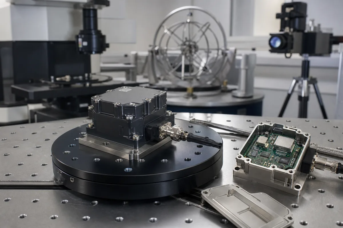
Representative product image. Confirm appearance and specifications with the manufacturer.

Product Specifications

Technical details and manufacturing context for Precision Inertial Measurement Unit (IMU) Sensor Module

Definition
The Precision Inertial Measurement Unit (IMU) Sensor Module is a compact, integrated component that combines accelerometers and gyroscopes to measure linear acceleration and angular rate across multiple axes. It serves as the fundamental motion-sensing core within larger navigation, guidance, and stabilization equipment, providing raw inertial data to a host system's processor for calculating position, orientation, and velocity. This module is critical for applications requiring precise motion tracking without external references, such as in industrial robotics, autonomous vehicles, and platform stabilization systems.

The module is built using micro-electromechanical systems (MEMS) technology, with silicon sensing elements mounted on a ceramic substrate and encapsulated in an epoxy molding compound for protection. It offers configurable measurement ranges: accelerometer range from ±2 to ±16 g, gyroscope range from ±125 to ±2000 °/s, and output data rates from 1 to 1000 Hz. The bandwidth is adjustable between 10 and 1000 Hz, and the nonlinearity is within ±0.1% of full scale. Bias stability for the gyroscope is 0.5 to 5 °/h, and for the accelerometer it is 0.01 to 0.1 mg, as measured by Allan variance. The module operates over a temperature range of -40 to 85 °C and requires a supply voltage of 3.0 to 3.6 V DC. It can survive shocks up to 10000 g for 0.1 ms when powered, and the sealed enclosure provides IP67 ingress protection per IEC 60529. The weight ranges from 10 to 20 g depending on the connector, and the digital interface supports SPI or I2C.

This component is intended for integration into larger systems; it does not include onboard processing for navigation solutions. The host system must implement algorithms to convert raw inertial data into useful motion information. When selecting this module, verify that the specific model's ranges, bias stability, and interface meet your application requirements. Confirm all specifications with the legal manufacturer or supplier, as values may vary by model and configuration. The listed standards are for reference only and do not imply certification of any specific product.
Working Principle
The IMU module uses MEMS accelerometers to detect linear acceleration via capacitive sensing of a proof mass. When the module accelerates, the proof mass displaces, changing capacitance, which is converted to a digital signal proportional to the applied force. MEMS gyroscopes detect angular rate using the Coriolis effect on vibrating structures. When the module rotates, the Coriolis force causes a displacement in the vibrating element, which is sensed capacitively and converted to a digital output. Both sensor outputs are digitized and made available via SPI or I2C interface for the host processor to read.
Common Materials
Silicon, Ceramic Substrate, Epoxy Molding Compound
Technical Parameters
ParameterTypical rangeNotes & selection driver
Accelerometer RangeRequired±2–±16 gFull-scale measurement range for linear acceleration
Gyroscope RangeRequired±125–±2000 °/sFull-scale measurement range for angular rate
BandwidthRequired10–1000 HzSensor signal output bandwidth
NonlinearityRequired±0.1 % of FSMaximum deviation from a best-fit straight line over the full range
Operating TemperatureRequired-40–85 °CAmbient temperature range for specified performance
Supply VoltageRequired3.0–3.6 VRequired DC input voltage for operation
Output Data Rate1–1000 HzConfigurable
Bias Stability0.5–5 °/hGyroscope, Allan variance
Accelerometer Bias Stability0.01–0.1 mgAllan variance
Shock Survival10000 gPowered, 0.1 ms
Ingress ProtectionIP67Sealed enclosureIEC 60529
Weight10–20 gDepends on connector
InterfaceSPI/I2CDigital output

Ranges are indicative industry figures for RFQ preparation, not a supplier commitment. Confirm every value and standard with the legal manufacturer before ordering.

Components / BOM
  • MEMS Accelerometer Die Part
    Measures linear acceleration via capacitive sensing of a silicon proof mass
    Material: Single-crystal Silicon
  • MEMS Gyroscope Die Part
    Measures angular rate via Coriolis effect on vibrating structures
    Material: Single-crystal Silicon
  • Application-Specific Integrated Circuit (ASIC)
    Conditions analog sensor signals, performs analog-to-digital conversion, and manages digital communication
    Material: Silicon (Semiconductor)
  • Hermetic Package Part
    Provides mechanical protection and a controlled internal environment for the MEMS dice
    Material: Ceramic

Industry Taxonomies & Aliases

Commonly used trade names and technical identifiers for Precision Inertial Measurement Unit (IMU) Sensor Module.

Industrial Ecosystem & Supply Chain Structure

Complementary Systems
Downstream Applications
Specialized Tooling

Application Fit & Sizing Matrix

Operational Limits
pressure: 0 to 1 atm (non-pressurized)
other spec: Vibration: 20g RMS, Shock: 2000g
temperature: -40°C to +85°C
Media Compatibility
✓ Aerospace navigation systems ✓ Robotic control platforms ✓ Marine vessel stabilization
Unsuitable: High-pressure hydraulic fluid environments
Sizing Data Required
  • Required measurement axes (3/6/9 DOF)
  • Maximum angular rate range (deg/s)
  • Required accuracy/resolution (deg/s, g)

Reliability & Engineering Risk Analysis

Failure Mode & Root Cause
Gyroscope/Accelerometer Drift
Cause: Thermal stress from repeated heating/cooling cycles degrading MEMS sensor stability, or contamination from outgassing of internal materials affecting micro-mechanical components.
Signal Degradation/Noise
Cause: Vibration-induced solder joint fatigue or connector fretting at interfaces, leading to intermittent electrical connections and compromised data integrity.
Maintenance Indicators
  • Unexplained bias or offset in sensor readings during system calibration checks
  • Increased noise levels or sporadic data dropouts in output signals during operation
Engineering Tips
  • Implement strict thermal management: Use controlled warm-up cycles before operation and maintain stable ambient temperatures to minimize thermal shock to MEMS components.
  • Apply vibration isolation mounting and conduct periodic torque checks on all mechanical/electrical connections to prevent loosening from operational vibrations.

Indicative industry ranges for design and RFQ preparation. Confirm the exact figures and applicable standard with the manufacturer before specifying.

Compliance & Manufacturing Standards

Applicable Standards
IEC 60068-2 Environmental Testing CE Marking - EMC Directive 2014/30/EU

Quoted from the published standard.

Manufacturing Precision
  • Gyroscope Bias Stability: +/- 0.5°/hr
  • Accelerometer Scale Factor: +/- 0.05%
Quality Inspection
  • Vibration Testing per MIL-STD-810G
  • Thermal Cycling Test (-40°C to +85°C)

Manufacturers of Precision Inertial Measurement Unit (IMU) Sensor Module

Manufacturer profiles associated with Precision Inertial Measurement Unit (IMU) Sensor Module.

Sourcing Precision Inertial Measurement Unit (IMU) Sensor Module from China?
Tell us your specification and target quantity — we will match it against manufacturer records and come back with the factories that fit.
Request manufacturers We manufacture this

Manufacturer listings support early research and capability understanding. They are not certification, ranking, or transaction guarantees.

Technical documentation
Request current drawings, revision history, and a signed specification sheet.
Manufacturing capability
Verify equipment lists, process limits, capacity, and representative production evidence.
Inspection readiness
Confirm test methods, calibrated equipment, sampling plans, and traceable reports.
Supplier transparency
Check the legal entity, factory address, ownership, certifications, and direct contacts.

CNFX does not score or rank suppliers. Buyers must verify all claims and documents with the legal manufacturer before ordering.

Frequently Asked Questions

What is the typical application of this IMU module?

This IMU module is designed for integration into navigation, guidance, and stabilization systems, such as in industrial robotics, autonomous vehicles, and platform stabilization. It provides raw inertial data that the host system's processor uses to calculate position, orientation, and velocity.

What are the available measurement ranges?

The accelerometer range is ±2 to ±16 g, and the gyroscope range is ±125 to ±2000 °/s. These ranges are configurable, but the exact values for a specific model must be confirmed with the manufacturer.

What is the output interface?

The module provides a digital output via SPI or I2C interface. The specific interface and protocol details should be verified in the product datasheet.

Does the module include onboard processing?

No, this module is a component that outputs raw inertial data. The host system must implement algorithms to convert this data into meaningful motion information, such as position and orientation.

Data Basis

Editorial classification, named public sources where available, and source-reviewed manufacturer records.

Preliminary Technical Classification
This page supports structured research, RFQ preparation, and supplier evaluation. It does not replace buyer-led supplier qualification, standards review, or technical approval.
Buyer enquiry

Request manufacturing insight for Precision Inertial Measurement Unit (IMU) Sensor Module

Ask for use case, specification boundaries, supplier type, and RFQ preparation information for this product.

Where it goes
Straight to the CNFX editorial desk, and to the manufacturer if this product is linked to a claimed profile. Nothing is broadcast to a supplier list.
Your details stay here
We do not sell or rent enquiry data, and we do not add you to a mailing list. Used only to answer this request.
No commission, no middleman
CNFX is a directory. We take no cut of any order and never negotiate on a supplier's behalf.
What we don't claim
A listing is not an endorsement. Qualify every supplier and verify every figure yourself before ordering.

Your business information is used only to process this request.

Thank you! Your message has been sent. We'll respond within 1–3 business days.
Sorry, we couldn't send your message. Please try again, or email us at contact@cnfx.com.

Need to Manufacture Precision Inertial Measurement Unit (IMU) Sensor Module?

Compare manufacturer profiles with relevant product and process capability.

Previous Product
Precision Rotary Encoder Disc
Last Product
Get QuotesChat