Editorial Technical Reference

Dampers

This page explains how Dampers is classified within Repair and Installation of Machinery and Equipment. Technical values and manufacturer relationships are research references; confirm the current specification and supplier evidence for each order.

Technical Definition & Core Assembly

Dampers are mechanical components installed in ducting systems to modulate, block, or direct the flow of air.
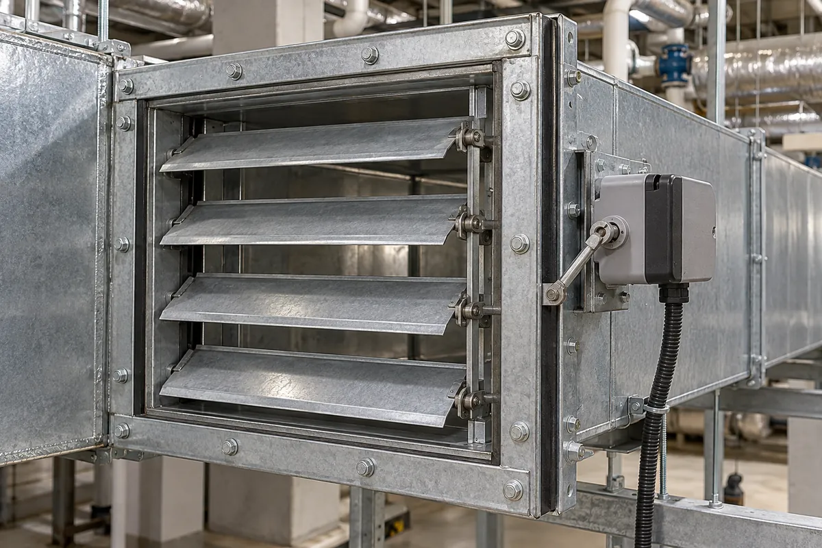
Representative product image. Confirm appearance and specifications with the manufacturer.

Product Specifications

Technical details and manufacturing context for Dampers

Definition
Dampers are mechanical components installed in ducting systems to modulate, block, or direct the flow of air. They are critical for controlling ventilation, balancing air distribution, isolating sections, and managing pressure within HVAC (Heating, Ventilation, and Air Conditioning) and industrial air handling systems. This directory entry covers dampers as a product type, with reference parameters typical for the category. The nominal size range is 100–2000 mm, matching duct dimensions per ISO 7805. Operating pressure is 1.0–1.6 MPa. Operating temperature is -20 to 80°C, as seals degrade above 80°C. Leakage rate is 0.5–2% (Class 3 or better for HVAC, per EN 1751). Actuator torque required for blade movement is 5–50 N·m. Actuator supply voltage is 24 V AC/DC ±10% (IEC 60038). Control signal is 0–10 V DC analog position command (IEC 60381). Ingress protection is IP54–IP65 (IEC 60529) for outdoor or washdown areas. Body material ranges from carbon steel Q235 to stainless steel 304 (GB/T 700, GB/T 1220). Blade material is 304–316 stainless steel (GB/T 1220) for corrosion resistance. Weight depends on size and material, ranging 5–150 kg. These are reference values; actual specifications must be confirmed with the manufacturer for the specific model and application. Dampers are used in various industries including repair and installation of machinery and equipment. They are essential for maintaining air quality, energy efficiency, and system safety. Proper selection requires consideration of duct size, pressure, temperature, and control requirements. Verification of compliance with standards is the responsibility of the buyer. Maintenance signals include increased leakage, sticking blades, or actuator failure. Failure boundaries include seal degradation, corrosion, or mechanical wear. Always consult the legal manufacturer for model-specific data and certification.
Working Principle
Dampers operate by using a movable blade, louver, or plate within the duct. An actuator (manual, electric, or pneumatic) adjusts the position of this element, changing its angle relative to the airflow. This alters the effective open area of the duct, thereby increasing or decreasing airflow resistance to regulate volume, pressure, or to completely shut off the flow. The actuator receives a control signal (e.g., 0–10 V DC) and supplies torque (5–50 N·m) to move the blade. The damper's leakage rate depends on the seal and blade design. In HVAC systems, dampers are used for zone control, fire isolation, and pressure management. In industrial settings, they handle larger volumes and harsher media. The operating principle is based on varying the cross-sectional area to create a pressure drop, which is a function of the blade angle and system characteristics. Proper actuator sizing is critical to overcome friction and dynamic forces. The damper must be installed with correct orientation and clearance for maintenance. The control system may include position feedback for precise modulation. The working principle is straightforward but requires careful engineering to ensure reliable operation over the specified temperature and pressure ranges.
Common Materials
Galvanized Steel
Technical Parameters
ParameterTypical rangeNotes & selection driver
Nominal Size100–2000 mmMatching duct dimensionsISO 7805
Operating Temperature-20–80 °CSeals degrade above 80°C
Leakage Rate0.5–2 %Class 3 or better for HVACEN 1751
Actuator Torque5–50 N·mRequired for damper blade movement
Actuator Supply Voltage24 ±10% V AC/DCStandard for building automationIEC 60038
Control Signal0–10 V DCAnalog position commandIEC 60381
Ingress ProtectionIP54–IP65For outdoor or washdown areasIEC 60529
Body MaterialQ235–304Carbon steel to stainless steelGB/T 700, GB/T 1220
Blade Material304–316Corrosion resistance for harsh mediaGB/T 1220
Weight5–150 kgDepends on size and material

Ranges are indicative industry figures for RFQ preparation, not a supplier commitment. Confirm every value and standard with the legal manufacturer before ordering.

Components / BOM
  • Frame Part
    Provides the structural housing that mounts within the duct and supports the blade assembly.
    Material: Galvanized Steel
  • Blade/Louver Part
    The adjustable element that rotates to modulate airflow. Multiple blades are often linked together.
    Material: Galvanized Steel or Aluminum
  • Shaft Part
    Connects and transfers rotational force from the actuator to the blades.
    Material: Steel
  • Seals/Gaskets Part
    Provide an airtight seal around the blade edges and shaft penetrations to minimize air leakage when closed.
    Material: Rubber or Neoprene
  • Linkage Part
    Mechanically connects multiple blades so they rotate in unison.
    Material: Steel

Applied To / Applications

This component is essential for the following industrial systems and equipment:

Industrial Ecosystem & Supply Chain Structure

Complementary Systems
Downstream Applications
Specialized Tooling

Application Fit & Sizing Matrix

Operational Limits
pressure: Up to 25 psi (standard), up to 100 psi with reinforced construction
flow rate: 0 to 50 m/s (velocity dependent on damper type and size)
temperature: -40°C to 400°C (typical), up to 800°C with special materials
slurry concentration: Not recommended for abrasive slurries >5% solids by weight without special wear protection
Media Compatibility
✓ Clean air/gas systems ✓ HVAC ducting ✓ Industrial exhaust gases
Unsuitable: Highly corrosive chemical environments without specialized coatings
Sizing Data Required
  • Duct dimensions (width/height/diameter)
  • Required pressure drop/flow control range
  • Actuation method and response time requirements

Reliability & Engineering Risk Analysis

Failure Mode & Root Cause
Seal degradation and leakage
Cause: Exposure to high temperatures, chemical corrosion, or abrasive particulates in the airflow, leading to hardening, cracking, or wear of elastomeric seals and gaskets.
Actuator or linkage failure
Cause: Mechanical wear, corrosion, or misalignment due to inadequate lubrication, excessive vibration, or over-torquing during operation or maintenance, resulting in binding, slippage, or complete disconnection.
Maintenance Indicators
  • Unusual grinding, squealing, or rattling noises during damper operation, indicating mechanical interference, worn bearings, or loose components.
  • Visible air leakage around the damper frame or blade seals during system operation, often detectable with smoke pencils or thermal imaging, signaling seal failure.
Engineering Tips
  • Implement a routine lubrication schedule for all moving parts (bearings, linkages, actuators) using manufacturer-recommended, temperature-stable greases to reduce friction and prevent corrosion.
  • Install particulate filtration upstream of the damper and perform regular duct cleaning to minimize abrasive wear on blades, seals, and bearings, extending component life.

Indicative industry ranges for design and RFQ preparation. Confirm the exact figures and applicable standard with the manufacturer before specifying.

Compliance & Manufacturing Standards

Applicable Standards
ISO 5211:2017 - Industrial valves - Part-turn actuator attachments ANSI/FCI 70-2-2013 - Control Valve Seat Leakage DIN EN 593:2017 - Industrial valves - Metallic butterfly valves for general purposes

Quoted from the published standard.

Manufacturing Precision
  • Bore diameter: +/-0.05mm
  • Flange flatness: 0.1mm per 300mm
Quality Inspection
  • Pressure testing for seat leakage (per ANSI/FCI 70-2)
  • Dye penetrant inspection for surface defects

Manufacturers of Dampers

Manufacturer profiles associated with Dampers.

Sourcing Dampers from China?
Tell us your specification and target quantity — we will match it against manufacturer records and come back with the factories that fit.
Request manufacturers We manufacture this

Manufacturer listings support early research and capability understanding. They are not certification, ranking, or transaction guarantees.

Technical documentation
Request current drawings, revision history, and a signed specification sheet.
Manufacturing capability
Verify equipment lists, process limits, capacity, and representative production evidence.
Inspection readiness
Confirm test methods, calibrated equipment, sampling plans, and traceable reports.
Supplier transparency
Check the legal entity, factory address, ownership, certifications, and direct contacts.

CNFX does not score or rank suppliers. Buyers must verify all claims and documents with the legal manufacturer before ordering.

Frequently Asked Questions

What are the typical size ranges for dampers?

The nominal size range is 100–2000 mm, matching duct dimensions per ISO 7805. The actual size must be selected based on the duct cross-section and airflow requirements. Confirm with the manufacturer for the specific model.

What is the operating pressure range?

The reference operating pressure is 1.0–1.6 MPa. Always verify the pressure rating for your application.

What temperature range can dampers handle?

The operating temperature range is -20 to 80°C. Seals degrade above 80°C, so for higher temperatures, special materials may be required. Check the manufacturer's specifications for temperature limits.

What is the leakage rate class?

The leakage rate is 0.5–2% (Class 3 or better for HVAC) per EN 1751. This indicates the amount of air that passes when the damper is closed. For tighter shut-off, lower leakage classes are available. Verify the class with the supplier.

Data Basis

Editorial classification, named public sources where available, and source-reviewed manufacturer records.

Preliminary Technical Classification
This page supports structured research, RFQ preparation, and supplier evaluation. It does not replace buyer-led supplier qualification, standards review, or technical approval.
Buyer enquiry

Request manufacturing insight for Dampers

Ask for use case, specification boundaries, supplier type, and RFQ preparation information for this product.

Where it goes
Straight to the CNFX editorial desk, and to the manufacturer if this product is linked to a claimed profile. Nothing is broadcast to a supplier list.
Your details stay here
We do not sell or rent enquiry data, and we do not add you to a mailing list. Used only to answer this request.
No commission, no middleman
CNFX is a directory. We take no cut of any order and never negotiate on a supplier's behalf.
What we don't claim
A listing is not an endorsement. Qualify every supplier and verify every figure yourself before ordering.

Your business information is used only to process this request.

Thank you! Your message has been sent. We'll respond within 1–3 business days.
Sorry, we couldn't send your message. Please try again, or email us at contact@cnfx.com.

Need to Manufacture Dampers?

Compare manufacturer profiles with relevant product and process capability.

Previous Product
Torque Verification Unit
Last Product
Get QuotesChat