Editorial Technical Reference

Ducting System

This page explains how Ducting System is classified within Machinery and Equipment Manufacturing. Technical values and manufacturer relationships are research references; confirm the current specification and supplier evidence for each order.

Technical Definition & Core Assembly

A network of conduits designed to transport airborne dust and particles from collection points to filtration units within a dust containment system.
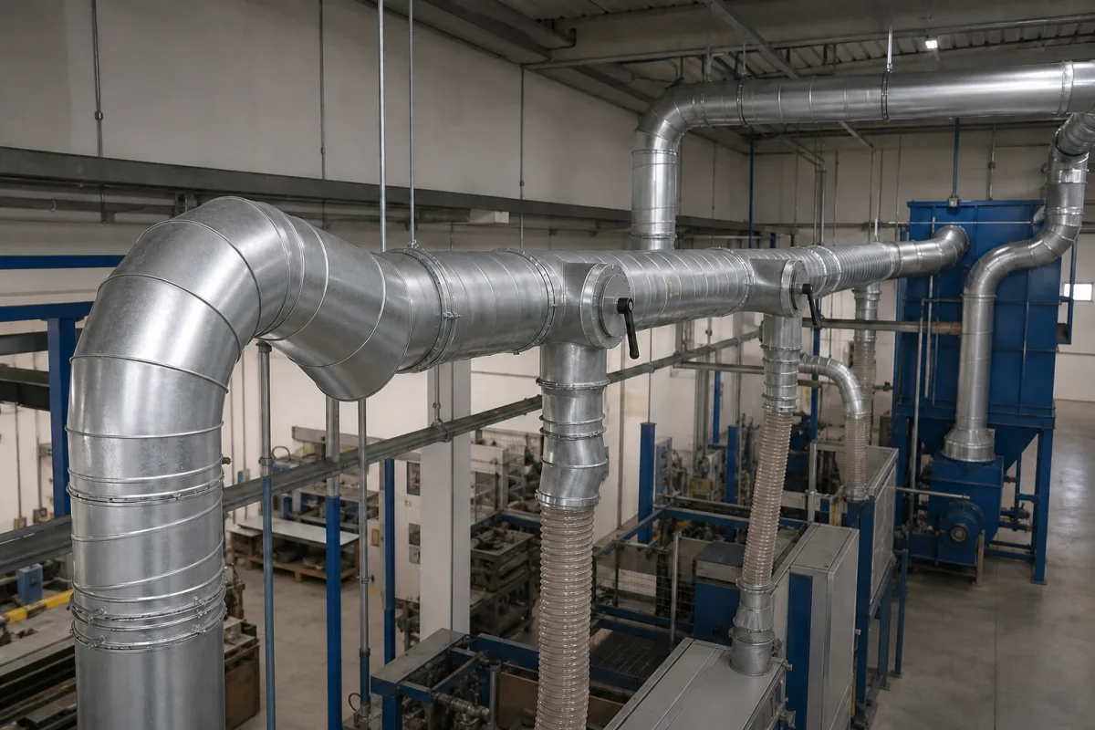
Representative product image. Confirm appearance and specifications with the manufacturer.

Product Specifications

Technical details and manufacturing context for Ducting System

Definition
The ducting system is a critical component of dust containment systems, consisting of interconnected pipes, tubes, and fittings that create sealed pathways for the controlled movement of dust-laden air. It serves as the transportation infrastructure that connects dust generation sources (such as grinding stations, cutting machines, or material handling points) to dust collectors, filters, or exhaust systems. Proper design ensures efficient airflow, minimizes pressure drops, prevents dust accumulation, and maintains containment integrity throughout the industrial process. The system is engineered with appropriate diameters, bends, and branch configurations to optimize airflow distribution while minimizing energy consumption and wear. Materials commonly used include galvanized steel, stainless steel, aluminum, and PVC for certain applications. Key parameters include nominal diameter (100–1000 mm), wall thickness (1.5–6.0 mm), operating pressure (1.0–1.6 MPa), operating temperature (-20–80 °C), air velocity (15–25 m/s), leakage rate (≤0.5% at 1.5× operating pressure), material grade (Q235B–304), surface treatment (epoxy–galvanized), flange standard (PN10–PN16), and weight (10–500 kg/m). These values are reference ranges and must be verified for the specific model and application. The system operates on principles of fluid dynamics and pressure differentials, with dust-laden air drawn into the network through hoods or capture points using induced draft from fans or blowers. The air travels through sealed conduits due to negative pressure created downstream, maintaining velocity to keep particles suspended and preventing settling. Proper design and maintenance are essential to ensure efficient operation and containment integrity. Always confirm model-specific values and standards with the legal manufacturer or supplier.
Working Principle
The ducting system operates on principles of fluid dynamics and pressure differentials. Dust-laden air is drawn into the duct network through hoods or capture points using induced draft from fans or blowers. The air travels through the sealed conduits due to negative pressure created downstream, maintaining velocity to keep particles suspended and preventing settling. The system is engineered with appropriate diameters, bends, and branch configurations to optimize airflow distribution while minimizing energy consumption and wear.
Common Materials
Galvanized steel, Stainless steel, Aluminum, PVC (for certain applications)
Technical Parameters
ParameterTypical rangeNotes & selection driver
Nominal Diameter100–1000 mmStandard sizes for dust collection systems
Wall Thickness1.5–6.0 mmThicker for abrasive materials
Operating Temperature-20–80 °CHigher temps require special seals
Air Velocity15–25 m/sPrevents particle settling
Leakage Rate≤0.5 %At 1.5× operating pressure
Material GradeQ235B–304Stainless for corrosive dustGB/T 700
Surface TreatmentEpoxy–GalvanizedCorrosion protectionISO 12944
Flange StandardPN10–PN16Matching pressure ratingISO 7005
Weight10–500 kg/mDepends on diameter and wall thickness

Ranges are indicative industry figures for RFQ preparation, not a supplier commitment. Confirm every value and standard with the legal manufacturer before ordering.

Components / BOM
  • Straight Duct Sections Part
    Primary conduits for dust transport over linear distances
    Material: Galvanized steel
  • Elbows/Bends Part
    Change direction of airflow while minimizing turbulence and pressure drop
    Material: Galvanized steel
  • Branch Fittings (Tees/Wyes) Part
    Combine or split airflow from multiple sources into main ducts
    Material: Galvanized steel
  • Dampers
    Regulate or shut off airflow in specific duct branches for system balancing
    Material: Galvanized steel with sealing gaskets
  • Flexible Connectors Part
    Absorb vibration and accommodate minor misalignment between equipment and ductwork
    Material: Reinforced fabric or metal bellows
  • Access Doors/Cleanouts
    Provide inspection and maintenance access for duct interior cleaning
    Material: Galvanized steel with gasketed seals

Applied To / Applications

This component is essential for the following industrial systems and equipment:

Industrial Ecosystem & Supply Chain Structure

Complementary Systems
Downstream Applications
Specialized Tooling

Application Fit & Sizing Matrix

Operational Limits
pressure: Up to 10 kPa (negative pressure typical for dust collection)
flow rate: Dependent on duct diameter and system design, typically 15-30 m/s air velocity
temperature: -20°C to 80°C
slurry concentration: Not applicable - designed for dry particulate transport only
Media Compatibility
✓ Wood dust and shavings ✓ Metal grinding dust ✓ Plastic particulate
Unsuitable: Corrosive chemical vapors or wet slurry applications
Sizing Data Required
  • Required air volume (CFM or m³/h)
  • Dust particle size and density
  • System static pressure requirements

Reliability & Engineering Risk Analysis

Failure Mode & Root Cause
Fatigue cracking at joints and supports
Cause: Cyclic thermal expansion/contraction and vibration-induced stress concentrations, often exacerbated by inadequate flexible connectors or improper support spacing.
Corrosion and erosion thinning
Cause: Chemical attack from aggressive process gases (e.g., acidic condensates, chlorides) combined with particulate abrasion, accelerated by moisture ingress and lack of protective coatings.
Maintenance Indicators
  • Audible: High-frequency whistling or rumbling indicating air leaks or excessive turbulence at damaged sections.
  • Visual: Visible sagging, misalignment, or oil/dust streaks at joints signaling loss of structural integrity or seal failure.
Engineering Tips
  • Implement regular thermographic surveys to detect hot spots from insulation breakdown or airflow restrictions before catastrophic failure.
  • Install vibration monitoring and pressure differential sensors at critical junctions to enable predictive maintenance and optimize cleaning cycles.

Indicative industry ranges for design and RFQ preparation. Confirm the exact figures and applicable standard with the manufacturer before specifying.

Compliance & Manufacturing Standards

Applicable Standards
ANSI/ASHRAE 120 - Method of Testing to Determine Flow Resistance of HVAC Ducts and Fittings DIN EN 1507 - Ventilation for buildings - Sheet metal air ducts with rectangular section - Requirements for strength and leakage

Quoted from the published standard.

Manufacturing Precision
  • Duct Diameter: +/- 0.5% of nominal dimension
  • Flange Flatness: 0.8mm per meter length
Quality Inspection
  • Leakage Test (Pressure Decay Method)
  • Dimensional Verification with Laser Scanning

Manufacturers of Ducting System

Manufacturer profiles associated with Ducting System.

Sourcing Ducting System from China?
Tell us your specification and target quantity — we will match it against manufacturer records and come back with the factories that fit.
Request manufacturers We manufacture this

Manufacturer listings support early research and capability understanding. They are not certification, ranking, or transaction guarantees.

Technical documentation
Request current drawings, revision history, and a signed specification sheet.
Manufacturing capability
Verify equipment lists, process limits, capacity, and representative production evidence.
Inspection readiness
Confirm test methods, calibrated equipment, sampling plans, and traceable reports.
Supplier transparency
Check the legal entity, factory address, ownership, certifications, and direct contacts.

CNFX does not score or rank suppliers. Buyers must verify all claims and documents with the legal manufacturer before ordering.

Supply Chain Compatible Machinery & Devices

Hydraulic Press

Industrial machine using hydraulic pressure to compress, form, or assemble materials

Explore Specs →
Heavy-Duty CNC Plasma Cutting Machine

The Heavy-Duty CNC Plasma Cutting Machine is a standalone industrial device designed for cutting conductive metals such as steel, stainless steel, aluminum, and copper alloys.

Explore Specs →
Automated Powder Coating System

Integrated industrial system for applying dry powder coatings to metal substrates.

Explore Specs →
Centrifugal Pump Impeller

The centrifugal pump impeller is a critical rotating component that converts mechanical energy from the motor into kinetic energy in fluid systems.

Explore Specs →

Frequently Asked Questions

What materials are commonly used for ducting systems?

Common materials include galvanized steel, stainless steel, aluminum, and PVC for certain applications. The choice depends on the dust characteristics, temperature, and corrosion resistance required.

What is the typical operating pressure range?

The reference range is 1.0–1.6 MPa, but this must be verified for the specific model and application.

How does air velocity affect performance?

Air velocity should be maintained between 15–25 m/s to prevent particle settling. Lower velocities may allow dust to deposit, while higher velocities increase wear and energy consumption.

What standards apply to ducting systems?

Standards such as GB/T 700, ISO 12944, and ISO 7005 are referenced for parameters like pressure, material grade, surface treatment, and flanges. Always confirm compliance with the manufacturer.

Data Basis

Editorial classification, named public sources where available, and source-reviewed manufacturer records.

Preliminary Technical Classification
This page supports structured research, RFQ preparation, and supplier evaluation. It does not replace buyer-led supplier qualification, standards review, or technical approval.
Buyer enquiry

Request manufacturing insight for Ducting System

Ask for use case, specification boundaries, supplier type, and RFQ preparation information for this product.

Where it goes
Straight to the CNFX editorial desk, and to the manufacturer if this product is linked to a claimed profile. Nothing is broadcast to a supplier list.
Your details stay here
We do not sell or rent enquiry data, and we do not add you to a mailing list. Used only to answer this request.
No commission, no middleman
CNFX is a directory. We take no cut of any order and never negotiate on a supplier's behalf.
What we don't claim
A listing is not an endorsement. Qualify every supplier and verify every figure yourself before ordering.

Your business information is used only to process this request.

Thank you! Your message has been sent. We'll respond within 1–3 business days.
Sorry, we couldn't send your message. Please try again, or email us at contact@cnfx.com.

Need to Manufacture Ducting System?

Compare manufacturer profiles with relevant product and process capability.

Previous Product
Z-axis Ram/Spindle
Last Product
Get QuotesChat