Editorial Technical Reference

Ductwork System

This page explains how Ductwork System is classified within Chemical Manufacturing. Technical values and manufacturer relationships are research references; confirm the current specification and supplier evidence for each order.

Technical Definition & Core Assembly

A network of ducts designed to transport exhaust gases from industrial processes to treatment or discharge points.
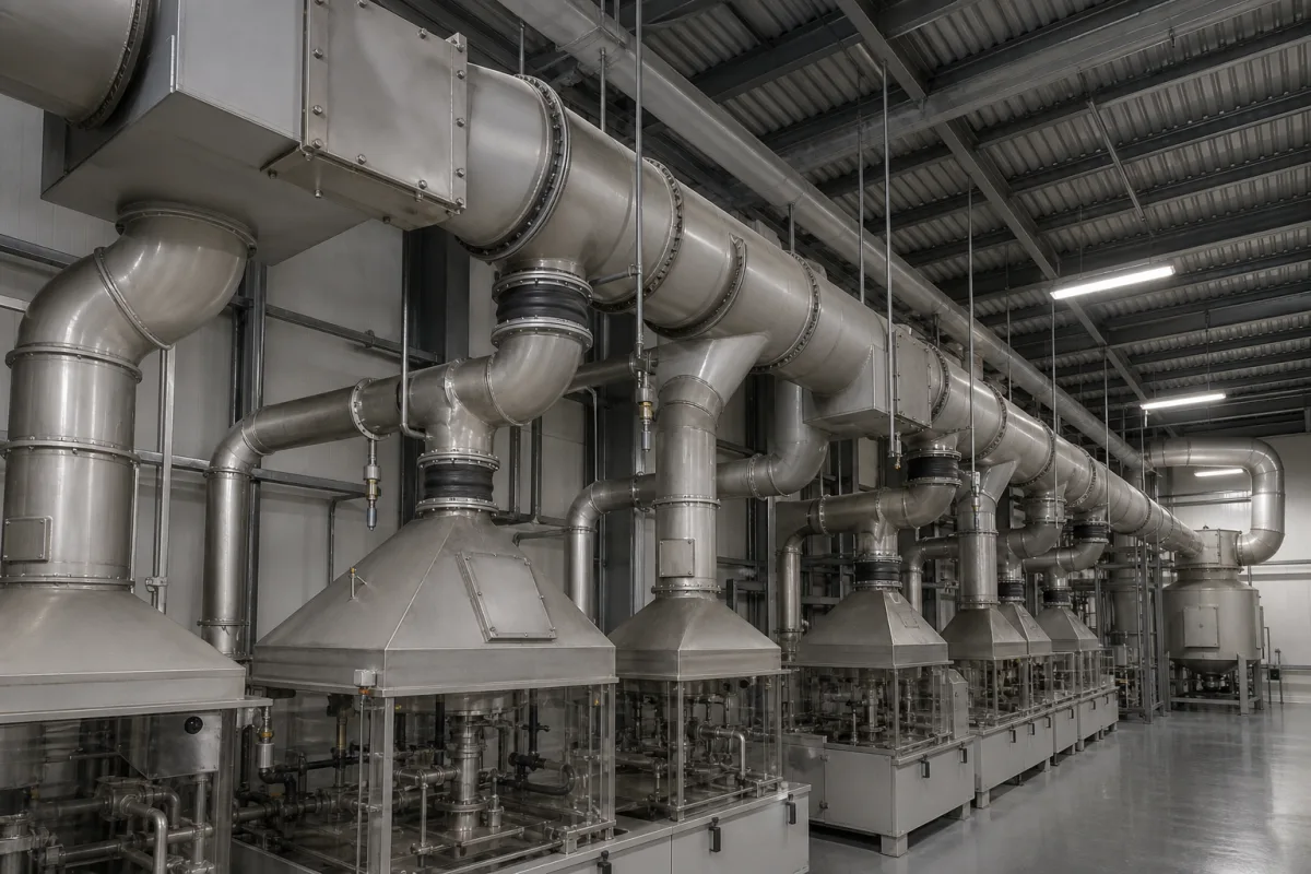
Representative product image. Confirm appearance and specifications with the manufacturer.

Product Specifications

Technical details and manufacturing context for Ductwork System

Definition
Within Exhaust Gas Management, the ductwork system serves as the critical transportation infrastructure that collects, channels, and directs exhaust gases from various emission sources (such as furnaces, reactors, or process equipment) through the treatment system (scrubbers, filters, etc.) and ultimately to the exhaust stack or discharge point. It ensures controlled flow, prevents gas leakage, and maintains system pressure balance. The system is engineered with proper sizing, routing, and supports to minimize pressure drops, prevent condensation, and resist corrosion while maintaining structural integrity under operational conditions. Materials on file include galvanized steel, stainless steel, and fiberglass reinforced plastic (FRP). Reference parameters include nominal diameter (100–2000 mm per ISO 4200), wall thickness (1.5–12 mm per ISO 4200), operating pressure (1.0–1.6 MPa), operating temperature (-40–200°C), leakage rate (0.1–1.0% per EN 12237), surface roughness (0.8–6.3 µm per ISO 4287), material grade (304–316L per ASTM A240), corrosion allowance (1.5–3.0 mm per ISO 15649), flange rating (PN10–PN40 per EN 1092-1), and weight (10–500 kg/m). These values are directory references and must be confirmed for the actual model and application. The ductwork system operates on principles of fluid dynamics and pressure differentials. Exhaust gases enter through collection hoods or inlets and flow through interconnected ducts due to negative pressure created by exhaust fans. Proper design ensures controlled flow, prevents leakage, and maintains pressure balance. Verification questions for procurement include confirming material compatibility with the specific gas composition, temperature, and pressure; checking compliance with relevant standards; and validating leakage rates and structural supports. Maintenance signals include increased pressure drop, visible corrosion, or leaks. Failure boundaries include structural collapse, excessive leakage, or blockage. Always verify model-specific values and standards with the legal manufacturer or supplier.
Working Principle
The ductwork system operates on principles of fluid dynamics and pressure differentials. Exhaust gases enter the system through collection hoods or inlets, then flow through interconnected ducts due to negative pressure created by exhaust fans. The system is designed with proper sizing, routing, and supports to minimize pressure drops, prevent condensation, and resist corrosion while maintaining structural integrity under operational conditions.
Common Materials
Galvanized steel, Stainless steel, Fiberglass reinforced plastic (FRP)
Technical Parameters
ParameterTypical rangeNotes & selection driver
Nominal Diameter100–2000 mmStandard sizes for ductworkISO 4200
Wall Thickness1.5–12 mmDepends on pressure and corrosion allowanceISO 4200
Operating Pressure1.0–1.6 MPa
Operating Temperature-40–200 °CMaterial dependent; above 200°C use special alloys
Leakage Rate0.1–1.0 %Class A to C; lower for hazardous gasesEN 12237
Surface Roughness0.8–6.3 µmSmoother for corrosive mediaISO 4287
Material Grade304–316L316L for chloride resistanceASTM A240
Corrosion Allowance1.5–3.0 mmBased on service life and mediaISO 15649
Flange RatingPN10–PN40Match operating pressureEN 1092-1
Weight10–500 kg/mDepends on diameter and wall thickness

Ranges are indicative industry figures for RFQ preparation, not a supplier commitment. Confirm every value and standard with the legal manufacturer before ordering.

Components / BOM
  • Straight Duct Sections Part
    Primary transport channels for exhaust gas flow
    Material: Galvanized steel
  • Elbows/Bends Part
    Change direction of gas flow with minimal turbulence
    Material: Stainless steel
  • Dampers
    Regulate or shut off gas flow in specific duct branches
    Material: Carbon steel
  • Expansion Joints
    Compensate for thermal expansion and vibration
    Material: Fabric or metal bellows
  • Support Hangers Part
    Provide structural support and maintain proper alignment
    Material: Steel

Applied To / Applications

This component is essential for the following industrial systems and equipment:

Industrial Ecosystem & Supply Chain Structure

Complementary Systems
Downstream Applications
Specialized Tooling

Application Fit & Sizing Matrix

Operational Limits
pressure: Up to 10 bar (gauge)
flow rate: 0.5 to 50 m³/s
temperature: -40°C to 400°C
slurry concentration: Up to 30% solids by weight
Media Compatibility
✓ Hot exhaust gases from combustion processes ✓ Dust-laden air from material handling ✓ Corrosive fume streams (with appropriate lining)
Unsuitable: High-velocity abrasive particulate streams exceeding 50 m/s
Sizing Data Required
  • Required volumetric flow rate (m³/s)
  • System pressure drop allowance (Pa)
  • Gas temperature and composition

Reliability & Engineering Risk Analysis

Failure Mode & Root Cause
Corrosion-induced perforation
Cause: Condensation accumulation, acidic/alkaline process gases, or galvanic corrosion from dissimilar metals in contact, leading to material thinning and eventual leaks.
Fatigue cracking at joints and supports
Cause: Cyclic thermal expansion/contraction, vibration from connected equipment, or inadequate support spacing causing stress concentration and crack propagation.
Maintenance Indicators
  • Visible rust streaks, moisture droplets, or white corrosion deposits on external surfaces, especially at seams and supports.
  • Audible rattling, banging, or whistling noises during operation, indicating loose components, internal obstructions, or excessive airflow turbulence.
Engineering Tips
  • Implement routine internal inspections using borescopes or access panels to detect early corrosion, and apply protective coatings (e.g., epoxy linings) compatible with the conveyed media.
  • Install expansion joints at strategic intervals to absorb thermal movement, and use vibration isolators or dampers at connections to fans, blowers, or other dynamic equipment.

Indicative industry ranges for design and RFQ preparation. Confirm the exact figures and applicable standard with the manufacturer before specifying.

Compliance & Manufacturing Standards

Applicable Standards
ISO 6947: Welding and allied processes - Joint preparation ANSI/SMACNA 006-2006: HVAC Duct Construction Standards - Metal and Flexible DIN 24194: Ductwork - Circular flanges for ventilation and air conditioning - Dimensions, materials, marking

Quoted from the published standard.

Manufacturing Precision
  • Bore diameter: +/- 0.5 mm for diameters up to 500 mm
  • Flatness of flange faces: 0.2 mm across any 300 mm length
Quality Inspection
  • Leakage test per ISO 5801: Industrial fans - Performance testing using standardized airways
  • Visual and dimensional inspection per SMACNA standards for seam integrity and squareness

Manufacturers of Ductwork System

1 company lists this product among what they make. Company figures are quoted from each company's own website; every card states where the relationship came from.

Chinafore
Hangzhou, Zhejiang, CN
Founded 2003250+ staff50,000 square meters
ISO 9001 ISO 14001
Also makes: Condensate Pump, Flexible Duct, Vacuum Pump and 4 more
Listed on the company's own website · profile compiled by CNFX from public sources

Manufacturer listings support early research and capability understanding. They are not certification, ranking, or transaction guarantees.

Technical documentation
Request current drawings, revision history, and a signed specification sheet.
Manufacturing capability
Verify equipment lists, process limits, capacity, and representative production evidence.
Inspection readiness
Confirm test methods, calibrated equipment, sampling plans, and traceable reports.
Supplier transparency
Check the legal entity, factory address, ownership, certifications, and direct contacts.

CNFX does not score or rank suppliers. Buyers must verify all claims and documents with the legal manufacturer before ordering.

Supply Chain Compatible Machinery & Devices

Automated pH Monitoring and Dosing System

Automated system for continuous pH monitoring and chemical dosing in process streams.

Explore Specs →
Automated Powder Dispensing and Blending System

Automated system for precise dispensing and homogeneous blending of powdered chemicals.

Explore Specs →
Automated Viscosity Control and Mixing System

The Automated Viscosity Control and Mixing System is an industrial automation solution designed for continuous monitoring and adjustment of viscosity in chemical mixing and blending operations.

Explore Specs →
Automated Catalyst Loading and Unloading System

The Automated Catalyst Loading and Unloading System is an integrated automation solution for the precise and safe transfer of catalyst materials in fixed-bed reactors, continuous stirred-tank reactors, and other catalytic process vessels.

Explore Specs →

Frequently Asked Questions

What materials are available for ductwork systems?

Materials on file include galvanized steel, stainless steel, and fiberglass reinforced plastic (FRP). The choice depends on the gas composition, temperature, and corrosion requirements. Always confirm material suitability with the manufacturer.

What are the typical operating pressure and temperature ranges?

Reference ranges are 1.0–1.6 MPa for operating pressure and -40–200°C for temperature. These are directory references; actual limits depend on the specific design and materials. Verify with the supplier.

How is leakage rate specified?

Leakage rate is referenced as 0.1–1.0% per EN 12237, with lower rates for hazardous gases. Confirm the required class for your application and ensure the system meets it.

What standards apply to ductwork components?

Standards referenced include ISO 4200 for dimensions, EN 12237 for leakage, ASTM A240 for material grades, and EN 1092-1 for flanges. These are procurement references; verify compliance with the manufacturer.

Data Basis

Editorial classification, named public sources where available, and source-reviewed manufacturer records.

Preliminary Technical Classification
This page supports structured research, RFQ preparation, and supplier evaluation. It does not replace buyer-led supplier qualification, standards review, or technical approval.
Buyer enquiry

Request manufacturing insight for Ductwork System

Ask for use case, specification boundaries, supplier type, and RFQ preparation information for this product.

Where it goes
Straight to the CNFX editorial desk, and to the manufacturer if this product is linked to a claimed profile. Nothing is broadcast to a supplier list.
Your details stay here
We do not sell or rent enquiry data, and we do not add you to a mailing list. Used only to answer this request.
No commission, no middleman
CNFX is a directory. We take no cut of any order and never negotiate on a supplier's behalf.
What we don't claim
A listing is not an endorsement. Qualify every supplier and verify every figure yourself before ordering.

Your business information is used only to process this request.

Thank you! Your message has been sent. We'll respond within 1–3 business days.
Sorry, we couldn't send your message. Please try again, or email us at contact@cnfx.com.

Need to Manufacture Ductwork System?

Compare manufacturer profiles with relevant product and process capability.

Previous Product
Twin-Screw Polymer Compounding Extruder
Last Product
Get QuotesChat