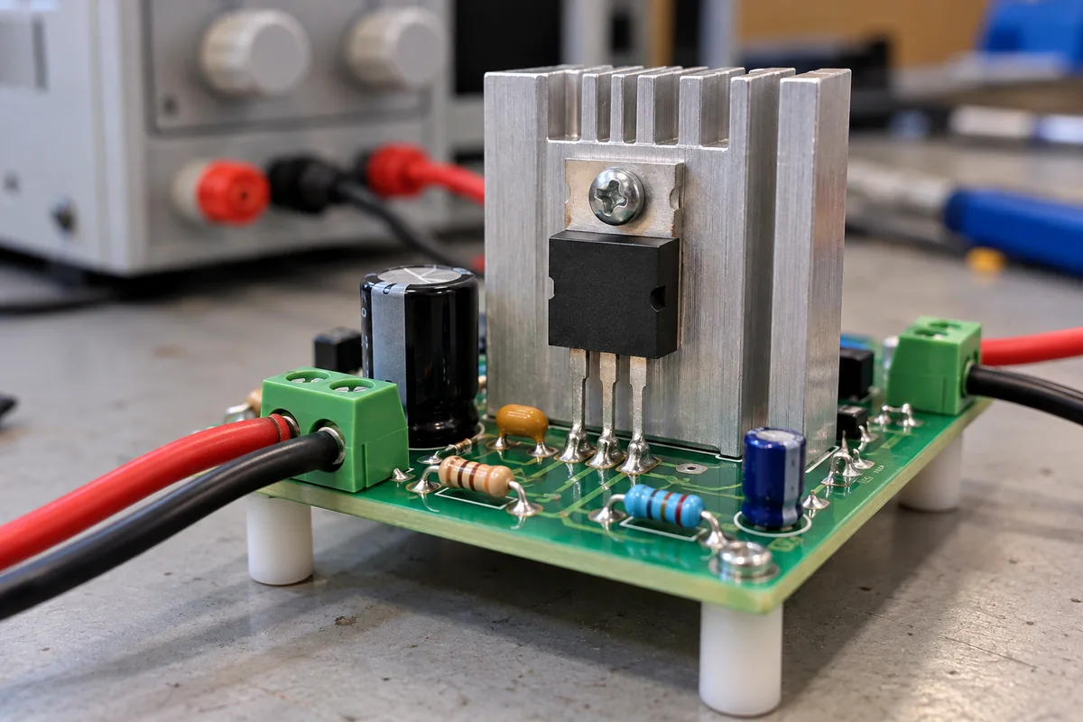
Active device on a heat sink: a TO-220 power transistor and the thermal path from its junction to the fins
TO-220 power transistors on a heat sink · junction-to-case and case-to-sink resistance, clip force and screw torque, greased, mica, alumina and silicone pad interfaces, power the tab can shed
In a linear regulator, motor driver or power supply built on through-hole parts, the active device that does the switching or amplifying is a single transistor in a TO-220 package, screwed or clipped to an aluminium heat sink. The device's data sheet rating assumes its metal tab is held at a known temperature; in practice the heat has to cross the tab-to-heat-sink interface, sometimes an insulator as well, and every one of those layers adds kelvins per watt. Specifying the device means specifying how it is mounted: clip or screw, how hard, with what compound or insulating pad.
Discrete through-hole active devices in TO-220 packages, chiefly power MOSFETs and power transistors, as mounted on a heat sink: their thermal resistances, mounting force and torque, and the greased, mica, alumina and silicone insulator interfaces between tab and heat sink. Monolithic transistor array ICs are covered on the Transistor array page; paralleled bipolar output stages of linear amplifiers, gate drivers, SiC MOSFET modules and low-dropout regulators have their own pages, as do aluminium heat sinks as a product and the heat sinks on which IGBT baseplate modules are mounted. RF and microwave active components, surface-mount packages and power modules are outside this page.
CNFX editorial research · Sources checked October 12, 2026 · 3 sources
Junction-to-case, case-to-sink and the power one TO-220 MOSFET can shed
Infineon's IRF540N, a 100 V, 44 mΩ power MOSFET in a TO-220 package, is rated 130 W at a case temperature of 25 °C with a linear derating factor of 0.87 W/°C and a maximum junction temperature of 175 °C. Its thermal resistances are 1.15 °C/W junction-to-case maximum, 0.50 °C/W case-to-sink on a flat, greased surface, and 62 °C/W junction-to-ambient maximum without a heat sink. [1]
Editorial calculation: 1 ÷ 1.15 °C/W is 0.87 W/°C, the data sheet's derating factor, and (175 − 25) °C ÷ 1.15 °C/W is 130 W, its power rating, so the 130 W figure assumes a case held at 25 °C. With the 0.50 °C/W greased interface added, junction-to-sink is 1.65 °C/W; with the heat sink surface at 80 °C, the device can dissipate (175 − 80) ÷ 1.65 ≈ 58 W at the limit. In free air, without a heat sink, 62 °C/W allows (175 − 25) ÷ 62 ≈ 2.4 W at 25 °C ambient. [1]
Nexperia states that the mounting-base-to-heat-sink resistance Rth(mb-h) depends on the package, not on the device, and applies to every device in a given package, while junction-to-mounting-base resistance is device-dependent and quoted in each data sheet. [2]
Ask the supplier for the device's junction-to-case resistance and the case-to-sink value for the mounting method you will use, then size the heat sink for the remaining temperature budget.
02
Greased, mica, alumina or silicone pad: what each interface adds per watt
Nexperia's mounting note for TO-220AB tabulates the mounting-base-to-heat-sink resistance for optimum conditions (flat heat sink, spring clip, the right amount of compound). [2]
Nexperia recommends an aluminium-oxide compound but warns that excess compound can give a higher thermal resistance than no compound at all; for insulated mounting the compound goes on the bottom of both the device and the insulator. [2] Editorial calculation: going from a dry tab (1.4 K/W) to a greased, clipped tab (0.3 K/W) removes 1.1 K/W, which at 20 W of dissipation is 22 °C off the junction.
Bergquist's Sil-Pad 900-S is a silicone insulating pad offered in TO-220 shapes and aimed at discrete packages such as TO-220, TO-247 and TO-218 mounted with spring clips, which apply limited pressure. The data sheet lists a thickness of 0.23 ± 0.025 mm, thermal conductivity of 1.6 W/m-K and thermal resistance of 0.2 °C-in²/W by ASTM D5470, and breakdown voltages of 5.5 kV AC with Type 1 electrodes and 8.3 kV AC with Type 3 electrodes. [3]
Clip force, M3 screw torque and heat-sink flatness for the tab
Nexperia gives a spring clip a minimum force of 10 N for good heat transfer and a maximum of 80 N to avoid damaging the device, and notes that clip mounting gives slightly lower thermal resistance than a screw and safe insulation for mains operation. [2]
The two makers' torque figures differ: Infineon's 1.1 N·m is above the 0.80 Nm maximum that Nexperia sets for its own TO-220AB devices. [1][2] Editorial note: use the torque in the data sheet of the device you are buying, not a generic TO-220 value, and ask for it when the data sheet does not give one.
Nexperia also says to fasten the device to the heat sink before soldering the leads, not to use self-tapping screws or pop rivets, to keep the washer off the plastic body, and not to solder the metal tab to the heat sink; wave soldering is limited to 260 °C more than 5 mm from the body for under 7 s. [2]
Paste it into your enquiry below or into an email to a maker, then replace every bracket.
Device: [MOSFET or bipolar; voltage; current; RDS(on) or VCE(sat)]
Package: [TO-220AB or full-pack TO-220F]
Thermal: [power dissipated; maximum heat sink temperature; junction-to-case required]
Mounting: [clip or M3 screw; force or torque; washer]
Interface: [compound; mica, alumina or silicone pad; insulation voltage]
Assembly: [mount before soldering; wave or hand soldering limits]
Explore company information and manufacturing capabilities, then discuss the scope of your project with a relevant supplier.
Share this page
Compiled and source-reviewed by the CNFX editorial team.
Each manufacturer above links to the page on that company's own website where the product is listed, with the date we checked it. How we source and review
· Page last updated 13 October 2026
Buyer questions
How much power can a TO-220 MOSFET dissipate on a heat sink?
Editorial calculation with Infineon's IRF540N: 1.15 °C/W junction-to-case plus 0.50 °C/W greased case-to-sink is 1.65 °C/W, so with the sink at 80 °C the junction reaches 175 °C at about 58 W. [1]
What torque should a TO-220 screw be tightened to?
Nexperia gives 0.55–0.80 Nm with a washer and 0.40–0.60 Nm against the tab for its devices; Infineon gives 1.1 N·m for the IRF540N. Follow the device's own data sheet. [2][1]
How much does an insulator add under a TO-220 tab?
Nexperia lists 0.3 K/W for a clipped, greased tab against 0.8 K/W with a 0.25 mm alumina or 0.05 mm mica insulator. [2]
What insulation does a silicone TO-220 pad give?
Bergquist lists 5.5 kV AC (Type 1 electrodes) breakdown for its 0.23 mm Sil-Pad 900-S. [3]
Sources and what still needs a direct check
Sources checked 2026-10-12. Infineon's IRF540N data sheet gives one TO-220 MOSFET's ratings and thermal resistances; Nexperia's application note AN11172 gives TO-220AB mounting data; Bergquist's Sil-Pad 900-S sheet, as distributed by Rapid Electronics, gives one insulating pad's properties.