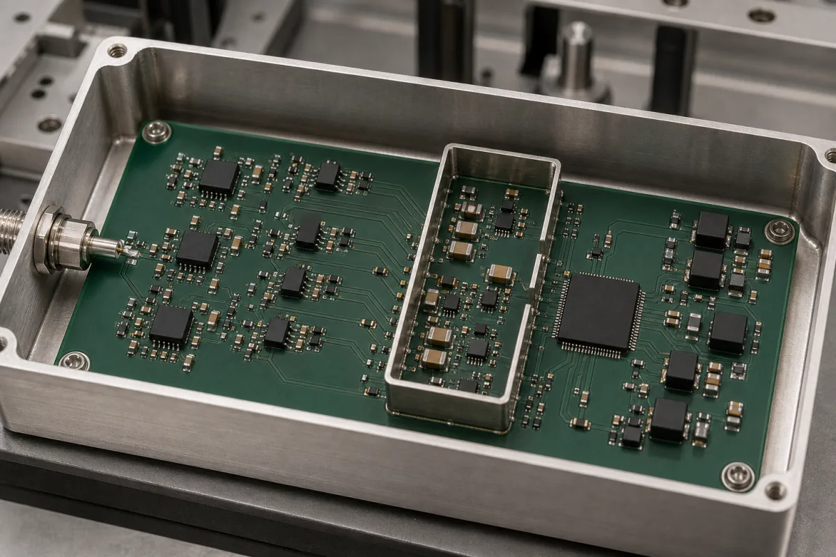
Analog front-end ICs that condition and digitise sensor signals · Channel count, ADC resolution and data rate, programmable gain, input-referred noise, CMRR, input bias current, supply rails, power per channel, temperature grade and package
An analog front-end (AFE) is an integrated circuit that sits between a sensor and a digital processor: it amplifies, filters and converts the sensor signal, and may also drive the sensor itself. Choosing one is a matter of matching it to the signal. Ask three things first: how many channels and what signal size and bandwidth you must capture, what noise and common-mode rejection the measurement needs, and what supply, power and temperature limits the product imposes.
Integrated analog front-end ICs supplied as components for sensor, biopotential, optical and instrumentation measurement. Stand-alone ADCs (see analog-to-digital converter chip), op-amps, complete data-acquisition modules and the sensors themselves are outside this page except where compared.
CNFX editorial research · Sources checked October 12, 2026 · 4 sources
Texas Instruments' ADS129x data sheet describes a family of multichannel, simultaneous-sampling 24-bit delta-sigma ADCs with built-in programmable gain amplifiers, internal reference and onboard oscillator; the ADS1298 has eight channels, data rates from 250 SPS to 32 kSPS and programmable gain of 1, 2, 3, 4, 6, 8 or 12, and it targets ECG, EMG and EEG instrumentation. [1]
The AFE4400 data sheet describes a different kind of AFE: an integrated front-end for pulse oximeters and optical heart-rate monitors that combines a low-noise receive channel with an integrated ADC, an LED transmit section with drive current programmable to 50 mA at 8-bit resolution, a timing controller, and diagnostics for photodiode and LED open or short and cable on/off detection; it also lists industrial photometry as an application. [2]
Editorial note: the two examples show that an AFE may only receive or may also drive the sensor, so state which functions you need integrated before comparing parts.
Give the supplier the sensor type and count, signal amplitude and bandwidth, required resolution and data rate, gain range, noise limit and bandwidth it is measured in, common-mode range and CMRR, any sensor excitation or LED drive needed, diagnostics, supply rails, power budget, temperature grade, package and the host interface.
02
Check noise, rejection, supplies, power and temperature grade
For the ADS129x, TI lists input-referred noise of 4 µVpp in a 150 Hz bandwidth at gain 6, input bias current of 200 pA, CMRR of −115 dB, 0.75 mW per channel, an analog supply of 2.7 V to 5.25 V and a digital supply of 1.65 V to 3.6 V; the BGA versions of the ADS129x are specified from 0°C to 70°C, while the ADS129xR BGA and ADS129x TQFP versions are specified from −40°C to +85°C. [1]
Editorial calculation: at 0.75 mW per channel, eight channels draw about 6 mW (8 × 0.75). [1]
For the AFE4400, TI lists a transmit dynamic range of 95 dB, a receive channel with 13 noise-free bits, receive supply current under 670 µA at 3.3 V, receive supply of 2.0 V to 3.6 V and transmit supply of 3.0 V to 5.25 V, and a specified range of 0°C to 70°C. [2]
03
Match the AFE to the signal size, and decide whether it needs a discrete low-noise stage in front
A 2019 Imperial College London paper sets out the amplitude and bandwidth of the bioelectrical signals an AFE has to capture, then shows one way to reach lower noise than an integrated converter alone: a discrete instrumentation-amplifier stage ahead of an ADS1298. The authors list EEG at 0.5–100 Hz and 1–20 µV, ECoG at 0.5–200 Hz and 5–100 µV, EMG at 7–500 Hz and 50 µV–2 mV, and ECG for monitoring at 0.5–40 Hz and 0.1–5 mV. [4]
Their design specification for the front end called for gain of at least 40 dB, integrated noise of at most 300 nV rms from 0.5 to 500 Hz, CMRR of at least 100 dB, DC tolerance of at least 50 mV, input dynamic range of at least ±2 mV, input impedance of at least 1 GΩ and current consumption of at most 5 mA. Each channel uses an AD8422 instrumentation amplifier at 40 dB gain (134 dB CMRR at that gain, 200 GΩ input impedance), an active first-order high-pass stage adding 20 dB, and a passive second-order low-pass filter, feeding the 8-channel 24-bit ADS1298. [4][1]
Measured, the front end gave 169 nV rms integrated noise over 0.5–500 Hz and a noise density of 8 nV/√Hz with the 1/f corner at about 5 Hz; the AFE's current consumption was about 2.5 mA, and the instrument ran at least 8 h on battery. The authors note a trade-off between the ultra-low power of research ASICs and the noise performance of their discrete AFE. Editorial calculation: 8 nV/√Hz × √(500 − 0.5 Hz) ≈ 179 nV rms, close to the measured 169 nV rms. If your signal is ECoG or EEG in the microvolt range, ask the supplier for integrated noise in your exact bandwidth and decide whether a front-end amplifier is needed. [4]
Consider configurable mixed-signal AFEs for monitoring and control
Not every AFE is a high-resolution biopotential converter. SGMICRO's SGM90508, listed in its AFE category, has 8 I/O pins that can each be configured as a 12-bit voltage DAC output, a current DAC output (4 channels), a 12-bit ADC input or a digital input or output, with an integrated 2.5 V reference (11 ppm/°C (typ.), off by default), an on-chip temperature sensor, supply monitoring and an I²C interface. [3]
Set this against the 24-bit, simultaneous-sampling biopotential AFEs above: the choice depends on whether the job is precise low-level signal capture (ECG, EEG, optical pulse) or monitoring and biasing a set of slower points such as laser bias and supply rails. [3][1][2]
Editorial calculation: with the 2.5 V reference, one 12-bit code step is 2.5 V / 4,096 ≈ 0.61 mV, against sub-microvolt steps for a 24-bit converter at gain.
Optical modules, industrial automation, general-purpose analog and digital I/O
State the signal type, number of channels, resolution and whether outputs (DAC or current bias) are also needed, and ask for the reference drift, ADC and DAC accuracy and interface.
05
PGA, ADC, reference, LED driver, diagnostics and interface blocks
The transmit driver row separates the two TI examples: the AFE4400 drives an LED as well as receiving, while the ADS1298 captures biopotential inputs. [2][1]
Explore company information and manufacturing capabilities, then discuss the scope of your project with a relevant supplier.
Share this page
Compiled and source-reviewed by the CNFX editorial team.
Each manufacturer above links to the page on that company's own website where the product is listed, with the date we checked it. How we source and review
· Page last updated 13 October 2026
Buyer questions
What does an analog front-end IC do?
It amplifies, filters and digitises sensor signals before a processor; one example combines eight PGAs and 24-bit delta-sigma ADCs with an internal reference and oscillator. [1]
Can an AFE drive the sensor as well?
Some do: an optical AFE for pulse oximeters integrates an LED driver programmable to 50 mA alongside its receive channel and ADC. [2]
How much power does a multichannel AFE use?
One 8-channel biopotential AFE is rated 0.75 mW per channel, about 6 mW for eight channels by editorial calculation. [1]
Is an AFE always a high-resolution sensor converter?
No: SGMICRO's SGM90508, for example, is a 12-bit configurable AFE whose 8 pins can each act as ADC input, voltage or current DAC output or GPIO, for optical modules and industrial I/O. [3]
How small are the signals a biopotential AFE must capture?
A 2019 Imperial College London paper lists EEG at 1–20 µV over 0.5–100 Hz and ECG at 0.1–5 mV over 0.5–40 Hz for monitoring. [4]
Sources and what still needs a direct check
Sources checked 2026-10-12. Three sources are makers' data sheets or product pages for specific AFE devices, cited as examples of the parameters an AFE specification covers, not endorsements; a 2019 Imperial College London paper gives signal amplitudes and measured noise for a discrete front end ahead of an integrated AFE.