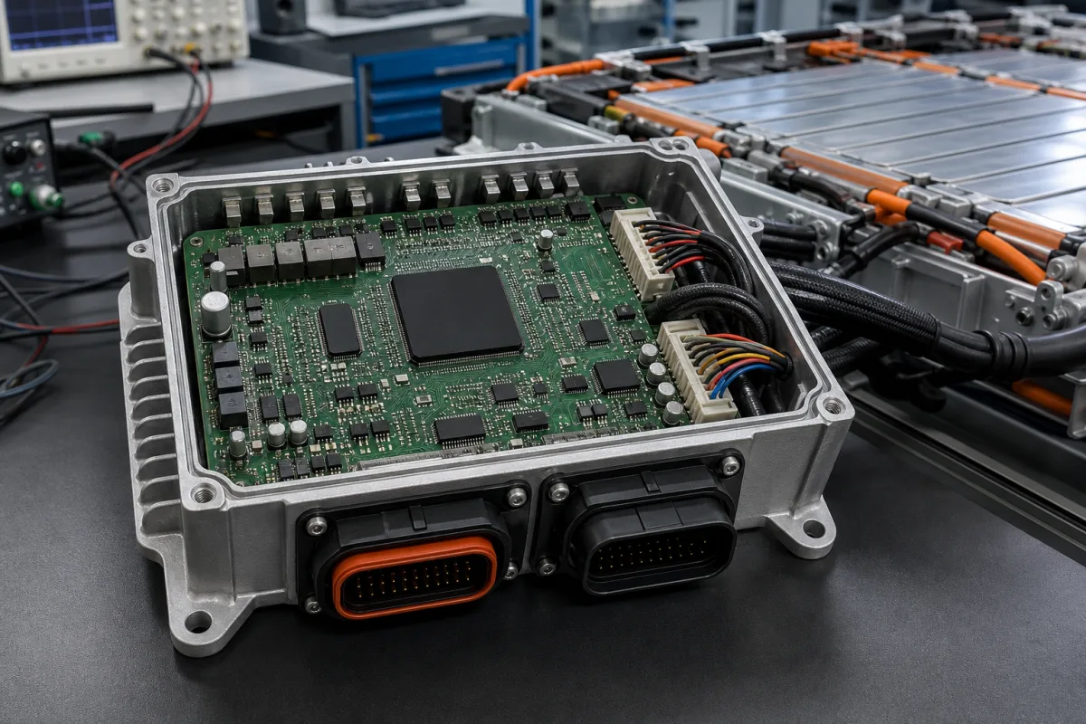
Battery control unit (BCU) with stack switchgear: the stack-level controller that measures stack current and voltage, pre-charges the DC bus and opens the contactors when a cell, current or temperature limit is crossed
The controller that decides when a battery stack connects and disconnects · contactors, pre-charge, current sensing, fuses and E-stop at the stack, trip thresholds, contactor life by breaking current, and the standards that make the unit interrupt the current
In a battery energy storage system, cell boards along each module measure voltages and temperatures; one unit per stack decides what to do with that information. This battery control unit, or stack controller with its switchgear, holds the main contactors, the pre-charge circuit that brings the bus up gently, the stack current sensor, fuses and the emergency-stop relay. Its specification is about switching more than measuring: up to what voltage and current it can connect a stack, at what thresholds it opens the contactors, how many times those contactors can break current before they wear out, and what the standards require it to interrupt.
Battery control units (BCUs), stack controllers and stack switchgear for lithium-ion battery stacks in stationary storage and similar systems: contactors and their breaking-current life, pre-charge, stack current and voltage sensing, fuses and E-stop, trip thresholds, insulation monitoring requirements, and their place between cell-monitoring modules and the system controller. Distributed master–slave BMS architectures, cell-board counts and scan rates are covered on the Distributed (master–slave) battery management system page; single-board BMS and protection boards on the Battery management system page; monitor ICs on the Battery monitoring IC page; active-balancing magnetics on the Balancing inductor and transformer page; stand-alone power contactors on the Power contactor page; electric-vehicle battery enclosures on the Battery enclosures page; float chargers for stationary lead-acid batteries on the Charging Controller page.
CNFX editorial research · Sources checked October 13, 2026 · 4 sources
Stack voltage and current: 1,250 V at 100 to 350 A continuous, overloads limited to 5 minutes an hour
Nuvation Energy's G4 High-Voltage BMS uses one Stack Switchgear unit per battery stack to connect it to the system's DC bus. The rack-mountable unit combines stack monitoring, electrical disconnects, pre-charging, current sensing, fuses and a safety relay for the E-stop, with power supplies, LEDs and front connectors; cell interface modules (12- or 16-channel) on the modules measure cell voltages and temperatures and balance cells. [1]
For the charge and discharge over-current that opens the contactors, Nuvation's table gives the continuous and absolute maximum values above; current above the continuous rating is allowed for no more than 5 minutes in each hour, never above the absolute maximum, and with time to cool afterwards. Stack over-voltage, cell over- and under-voltage and over- and under-temperature thresholds are configurable and also open the contactors, with the stack over-voltage threshold configurable up to 1,250 V DC. The unit runs at −10 to 50 °C where it is not accessible in the end installation, but only at 10 to 40 °C where it is, at up to 2,000 m altitude and 5–85 % relative humidity. [1] Editorial calculation: 5 minutes per hour is about 8 % of operating time above the continuous rating. [1]
Nuvation's G5 platform raises the stack voltage to 1,500 V DC with current configurations of 200, 300 and 350 A, CI-24 and CI-36 cell interface configurations and higher cell-count configurations including 52s and 104s, for lithium-ion cells from 1.6 to 4.3 V. [2]
G4 Stack Switchgear (1,250 V DC)
Continuous current
Absolute maximum current
Maximum breaking current of contactors
NUVSSG-1250-100
100 A
150 A
150 A
NUVSSG-1250-200
200 A
250 A
250 A
NUVSSG-1250-300
300 A
350 A
350 A
NUVSSG-1250-350
350 A
400 A
400 A
State the stack voltage range, continuous charge and discharge current, peak current and how long it lasts, the installation temperature range and whether the unit will be accessible, and the certifications the system must meet (for example UL 1973 and UL 9540).
02
Contactor life is counted in openings under load: 6,000 below 100 A, 100 up to the rated breaking current, one above it
The contactors in the G4 Stack Switchgear wear according to the current they break. Nuvation tabulates the same pattern for every current rating: at least 6,000 opening cycles below 100 A, 100 cycles between 100 A and the rated maximum breaking current, one cycle above it, and a single break of up to 1,260 A as the absolute limit. The firmware tracks contactor life, which degrades when contactors open at elevated load current. [1]
To keep breaks small, a disconnect delay can be configured so that the power conversion system reduces the stack current before the contactors open; the delay is bypassed and contactors open at once when the switchgear loses power. [1] Editorial calculation: 6,000 openings below 100 A against 100 between 100 A and the rated maximum is a factor of 60 in contactor life, which is why the disconnect delay matters on a stack that trips under load. [1]
A smaller, second-life installation shows the same layering in simpler form: a monitoring interface for a repurposed EV battery used a relay board to drive an external Omron G9EC1 high-voltage contactor (400 V, 200 A DC) that interrupts current on an alarm or error, kept the 24 V relay circuit and the high-voltage contactor circuit physically separate, and mounted the contactor outside the battery pack to avoid noise coupling and false triggers. [4]
Contactor rating (NUVSSG-1250, all current versions)
Ask for contactor life by breaking current, whether a disconnect delay can be coordinated with the PCS, how contactor wear is logged, and how the E-stop and high-voltage circuits are separated.
03
What the standards make a BCU do: interrupt at the upper cell voltage, monitor current and cell temperatures, and meet insulation limits
A 2025 review of standards and regulations for battery management systems in Germany (Global Challenges) treats the BMS, battery management unit and battery control unit as names for the same safety function, and collects what standards require of it. [3]
The review notes that insulation monitoring is assigned to the BMS in certain applications, with threshold values that depend on whether the system is AC or DC and on its architecture, and that the BMS's measurement accuracy has to be good enough to detect any violation of the safe operating area at all times. [3] Editorial calculation: the 1 MΩ limit at 500 V corresponds to 2,000 Ω per volt; it is quoted for systems up to 500 V and does not by itself set a limit for a 1,250 or 1,500 V stack. [3]
Nuvation lists UL 1973 recognition for the internal power interface and stack controller modules of its G4 switchgear, with UL 991 and UL 1998 functional-safety recognition and IEC 62368-1 and -3 for electrical safety. [1]
Requirement (as summarised in the review)
Standard
Interrupt current if cell temperature or current exceeds safety limits
DIN EN IEC 63115-2, DIN EN IEC 62619
Interrupt current before or as soon as cell voltage reaches its upper safety threshold
DIN EN IEC 62619
Interrupt on overcharge, deep discharge or overheating for stationary storage batteries
ISO 6469-1, VDE-AR-E 2510-50, DIN EN IEC 62485-5
Monitor cell or cell-block voltages, system current and cell-level temperatures; validate measurement accuracy against a calibrated test bench
VDE-AR-E 2510-50
Minimum insulation resistance of 1 MΩ for systems up to 500 V nominal (pre-commissioning)
DIN VDE 0100-600
Voltage class A below 30 V AC or 60 V DC as one criterion for no hazardous voltage after a crash
UN GTR 20, ECE R 100, ISO 6469-4
List the standards the battery system must meet, and ask the supplier which interruption functions, insulation monitoring and measurement-accuracy validation the BCU itself provides and which are left to other equipment.
04
BCU details to send
Paste it into your enquiry below or into an email to a maker, then replace every bracket.
Stack: [chemistry; series cell count; voltage range]
Current: [continuous charge/discharge; peak and duration]
Switchgear: [contactors; pre-charge; fuses; E-stop; current sensor]
Thresholds: [cell and stack voltage; current; temperature]
Contactor life: [expected trips under load; disconnect delay with PCS]
Insulation: [monitoring required; threshold]
Environment: [temperature; accessibility; altitude]
Standards: [UL 1973; UL 9540; IEC 62619; others]
Explore company information and manufacturing capabilities, then discuss the scope of your project with a relevant supplier.
Share this page
Compiled and source-reviewed by the CNFX editorial team.
Each manufacturer above links to the page on that company's own website where the product is listed, with the date we checked it. How we source and review
· Page last updated 13 October 2026
Buyer questions
What does a battery control unit include?
In Nuvation's G4 system, the per-stack switchgear includes stack monitoring, contactors, pre-charge, current sensing, fuses and an E-stop safety relay, working with cell interface modules on the battery modules. [1]
How long can a BCU carry current above its continuous rating?
Nuvation allows charge or discharge current above the continuous rating for no more than 5 minutes per hour and never above the absolute maximum (for example 250 A on the 200 A version). [1]
How many times can BCU contactors open under load?
Nuvation rates them for at least 6,000 openings below 100 A, 100 between 100 A and the maximum breaking current, and one above it, with a one-time limit of 1,260 A. [1]
When must a BMS or BCU interrupt the current?
Standards summarised in a 2025 review require interruption when cell temperature or current exceed limits and, under IEC 62619, before or as soon as cell voltage reaches its upper safety threshold. [3]
Sources and what still needs a direct check
Sources checked 2026-10-13. Four sources from three publishers: Nuvation Energy's G4 High-Voltage BMS datasheet and G5 product page, a 2025 Global Challenges review of standards and regulations for battery management systems, and a 2022 Sensors paper on monitoring a second-life EV battery with an external high-voltage contactor.