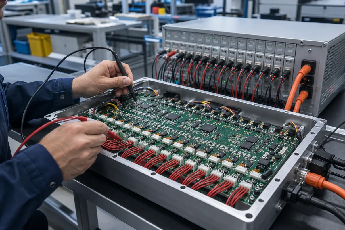
Battery electronics · Cell measurement, SOC estimation, current sensing, balancing and protection
A battery management system monitors and protects the cells in a battery pack and estimates how much charge remains. Ask three things first: which chemistry and how many cells in series, what continuous and peak current, and how accurate the state of charge and protection must be.
Battery management systems and protection boards for lithium-ion, LFP and LTO packs in industrial, energy-storage and vehicle use. Battery cells, complete packs, BMS test equipment and chip-level components are outside this page.
CNFX editorial research · Sources checked October 11, 2026 · 4 sources
Monolithic Power Systems, a chip maker, describes a BMS as a battery monitor and protector, a fuel gauge and a main controller. State of charge cannot be measured directly and must be estimated: coulomb counting integrates measured current, so any current error is integrated too and the estimate drifts unless corrected; model-based methods that use current, voltage and temperature help it converge. [1]
Editorial calculation: if current sensing has a 0.5% full-scale offset on a 100 A range, that is 0.5 A; over 10 hours it adds up to 5 Ah, or 5% of a 100 Ah pack, unless the estimate is corrected. [1][2]
Ask suppliers for cell-voltage accuracy across temperature, current accuracy and offset, and how SOC is corrected, not only a headline SOC error.
Give the supplier the chemistry, series and parallel cell count, pack voltage, continuous and peak current, required SOC and voltage accuracy, temperature range, balancing need, communication protocol, enclosure and certifications.
02
Match the BMS to chemistry and functions
Writing in Electronic Design, Alan Earls notes that LFP cell voltage changes only tens of millivolts between about 20% and 80% SOC, so voltage alone cannot estimate SOC, small measurement errors become large SOC errors, and top-of-charge voltage balancing is less informative; coulomb counting becomes the primary estimator. [2]
He suggests current sensing with 0.5% full-scale error or better, low-drift references, offset calibration during rest, hybrid models such as Kalman filters, a narrower cell-measurement span, 16-bit converters and tighter channel matching, and notes that a 5 mV error tolerable with NMC can mask SOC or balancing decisions with LFP. [2]
Functions vary by product: Yixinyuan's BMS boards, for example, list cell voltage, temperature and high-voltage detection, balancing, CAN, RS485, TTL and Bluetooth communication and sleep and wake control; one 21- to 30-series board lists 170 A continuous and 425 A for 10 seconds. [3]
03
Ready boards from Yixinyuan and Daly, design-and-build from AYAA
Yixinyuan lists BMS boards from 8 to 32 series with CAN, RS485 and Bluetooth [3]; according to the pages linked on their cards, Daly lists LiFePO4 and vehicle BMS and active balancers, BAK lists BMS and protection boards with battery packs, AYAA offers BMS design and circuit-board manufacturing, and Eshine lists BMS among distributed electronic components.
04
Ask which monitor IC the board uses and check its datasheet
Texas Instruments' product page for the BQ76952 battery monitor and protector shows what a monitor IC datasheet states. The chip covers 3-series to 16-series Li-ion, Li-polymer and LiFePO4 packs, with cell voltage measurement error under 10 mV (typ.), coulomb-counter input offset error under 1 µV (typ.), a ±200 mV current-measurement range across the sense resistor, and temperature sensing with an internal sensor and up to nine external thermistors. [4]
The page lists Vin (max) of 80 V, an operating temperature range of −40 to 85 °C, and supply currents (typ.) of 286 µA in NORMAL mode, 24 µA to 41 µA in SLEEP, 9 µA to 10 µA in DEEPSLEEP and 1 µA in SHUTDOWN. It supports autonomous or host-controlled cell balancing and 400 kHz I2C, SPI and HDQ one-wire communication. [4]
Editorial note: these are datasheet (typ.) values for one chip, given as an example, not a guarantee for a finished board. Electronic Design notes that a 5 mV error tolerable with NMC can mask SOC or balancing decisions with LFP [2], so ask the BMS supplier which monitor IC is fitted, and for the maximum accuracy over temperature and the standby current of the whole board.
Power switching, including relay types; sense harness. [3]
Continuous and peak current.
06
Pack values a BMS maker has to see before quoting
Only the accuracy, SOC, interface and cell-count rows carry a published reference; the two LFP accuracy rows are Electronic Design's suggestions, not a standard.
Paste it into your enquiry below or into an email to a maker, then replace every bracket.
Pack: [chemistry; series and parallel count; voltage range; capacity]
Current: [continuous; peak and duration; charge current]
Accuracy: [cell voltage; current; SOC and correction method]
Balancing: [passive or active; current]
Protection: [over and under voltage, over current, short circuit, temperature limits]
Comms: [CAN, RS485, Bluetooth; protocol]
Environment: [temperature; IP rating; certifications]
Daly lists LiFePO4 and vehicle BMS with active balancers; Yixinyuan lists 8- to 32-series boards; BAK sells BMS and protection boards with its battery packs; AYAA offers BMS design and circuit-board manufacturing; Eshine distributes BMS among other electronic components.
Daly Electronics
Manufacturing site to be confirmed for the order
Lists LiFePO4 and vehicle BMS and active balancers.
Explore company information and manufacturing capabilities, then discuss the scope of your project with a relevant supplier.
Share this page
Compiled and source-reviewed by the CNFX editorial team.
Each manufacturer above links to the page on that company's own website where the product is listed, with the date we checked it. How we source and review
· Page last updated 13 October 2026
Buyer questions
Why is SOC accuracy harder with LFP batteries?
LFP voltage changes only tens of millivolts between about 20% and 80% SOC, so voltage alone cannot pin down SOC and coulomb counting carries the load. [2]
Why does coulomb counting drift?
It integrates measured current, so any current error accumulates; a 0.5 A offset over 10 hours adds 5 Ah. [1]
What does a BMS consist of?
A battery monitor and protector, a fuel gauge that estimates SOC, and a main controller. [1]
What cell-voltage accuracy does a BMS monitor chip state?
Texas Instruments lists cell voltage measurement error under 10 mV (typ.) for its BQ76952 3- to 16-series monitor; ask the BMS supplier for the maximum over temperature as well. [4]
Sources and what still needs a direct check
Sources checked 2026-10-11. Monolithic Power Systems is a BMS chip maker. The Electronic Design article is trade journalism. Yixinyuan is a supplier listed on this page.