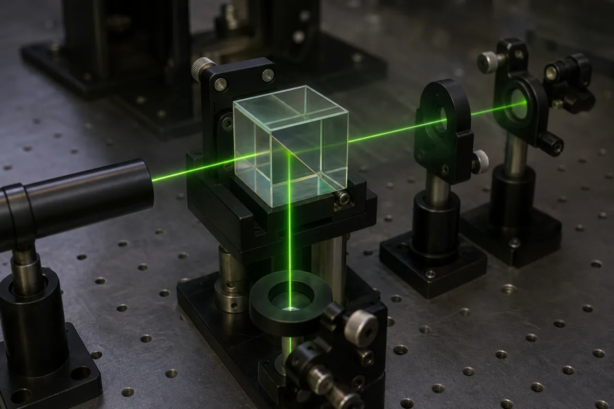
Optics · Cube or plate, polarizing, non-polarizing or dichroic, split ratio, extinction ratio and polarization sensitivity
A beam splitter divides a light beam into two at a set ratio, or combines two beams into one, using a coated surface inside a cube or on a plate. Ask three things first: whether a cube or plate suits your layout, how it must treat polarization and wavelength, and the split ratio, extinction ratio, surface quality and damage threshold it guarantees.
Free-space optical beam splitters: cube and plate, standard, polarizing, non-polarizing and dichroic types, and beam splitter coatings on custom optics. Fibre-optic splitters and couplers, RF power dividers and complete optical modules are outside this page.
CNFX editorial research · Sources checked October 12, 2026 · 4 sources
Edmund Optics' application note describes cube beam splitters as two right-angle prisms with the hypotenuse of one coated and the two cemented together; light should enter the coated prism (which may be marked on a ground face) to avoid damaging the cement. Cubes integrate easily at 0° angle of incidence, have no beam shift and equal reflected and transmitted path lengths, but are heavy and harder and costlier to make large. Plate beam splitters are a thin coated plate designed for 45°, which may carry an anti-reflection coating on the second surface; they are light, cheaper and easier to make large, but their reflected and transmitted paths differ, the transmitted beam shifts, and 45° alignment can take time. [1]
02
Choose polarization behaviour, split ratio and extinction ratio
Standard beam splitters split unpolarized light at a set reflection/transmission (R/T) ratio with unspecified polarization behaviour; polarizing beam splitters reflect S-polarized and transmit P-polarized light; non-polarizing beam splitters keep the incident polarization at the design ratio; dichroic beam splitters split by wavelength, for example in fluorescence systems. Some are also specified by extinction ratio, Tp/Ts, which is almost always better than the reflected ratio Rs/Rp because reflected light is not free of P-polarization. [1]
Edmund's polarization FAQ adds that at 45° the S state is reflected more and the P state less than average; plate beam splitters' S and P transmission can each vary by as much as 20% from the average at 550 nm for a visible coating, dichroic cubes can show S–P differences up to 70%, polarizing cubes can reflect 92% of S-polarized light at 632.8 nm, and non-polarizing beam splitters are "typically optimized for a specific laser wavelength with the s- and p-polarization states of the transmitted beam differing by less than 5%". [2]
Editorial calculation: a polarizing cube reflecting 92% of S-polarized light leaves up to 8% of the S component in the transmitted arm, so state the extinction you need in each output arm, not only the R/T ratio. [2][1]
Give the supplier the wavelength or band, angle of incidence, beam size and divergence, polarization of the input, split ratio and tolerance, extinction ratio for each arm, surface quality and flatness, laser power or pulse energy, mounting, size and environment.
03
Compare what suppliers offer
Suppliers linked to this page list free-space beam splitters or beam splitter coatings; each card links to the page reviewed.
Hitronics lists polarizing and non-polarizing beam splitter prisms; Focuslight, Lumina and Bena list beam splitter prisms with other precision optics; Alpha Optics lists broadband and polarizing beam splitter coatings on cubes; UNI Optics lists beam splitter coatings on custom optics.
04
Specify a laser-grade polarizing cube by its measured limits
For pulsed-laser work, EKSMA Optics' specification for its high energy polarizing cube beamsplitters shows the values a buyer can hold a maker to. The cubes are optically contacted for high power applications rather than cemented, are made of UV fused silica for laser lines, and have an anti-reflection coating on all four outer faces. [3] EKSMA's specification table gives a laser damage threshold of ">15 J/cm²" for 10 ns pulses at 1064 nm (the product description on the same page says "up to 15 J/cm²", so confirm which figure applies), reflection of s-polarization above 99.5%, and transmission of p-polarization above 97% for laser-line versions against above 90% for broadband versions. [3] The same sheet gives an extinction ratio of >1:500, so the extinction figure belongs in the order next to the R and T values. [3]
Editorial note: a damage threshold is only comparable when the pulse length, repetition rate and wavelength match; EKSMA quotes its figure at 10 ns, 10 Hz and 1064 nm, so ask other suppliers for the threshold under the same conditions or under the conditions of your laser. [3]
Read a non-polarizing cube specification line by line
Hangzhou Shalom EO's non-polarizing beamsplitter cube page shows how a metal-dielectric (hybrid) cube is specified. The cube is two right-angle glass prisms with a hybrid metallic-dielectric coating at the interface and anti-reflection coatings on the four entry and exit faces. Shalom EO states that the metal content in the hybrid coating gives the cube a much lower damage threshold and says such cubes are "not so great at handling high-power lasers". [4]
Editorial calculation: T/R = 46/46 adds up to 92%, so about 8% of the input is neither transmitted nor reflected in the two output arms; ask each supplier for T + R at your wavelength. With an 80% clear aperture on a 12.7 mm cube, the usable width is about 10.2 mm, so a beam with wings wider than that should move up to the next size. [4]
Set this sheet beside the EKSMA high energy polarizing cube above: EKSMA's table gives ">15 J/cm²" at 10 ns (its product description says "up to 15 J/cm²"), while Shalom EO gives no threshold figure and says such cubes are "not so great at handling high-power lasers", so ask for a measured threshold whenever a laser is involved. [3][4]
Shalom EO item
Stated value
What to compare
Wavelength bands
450–650 nm standard; 650–950, 900–1200 and 1200–1600 nm on inquiry [4]
Fill the specification fields with values for your optics
A beam splitter quotation needs values for your beam and layout. The table explains each field, gives published values where a reviewed source states them, and says what to obtain from the supplier.
Send the beam, polarization and layout data together
Paste it into your enquiry below or into an email to a maker, then replace every bracket.
Beam: [wavelength; diameter; divergence; power or pulse energy]
Geometry: [AOI; cube or plate; mounting]
Split: [R/T; tolerance; for S and P]
Polarization: [input state; extinction ratio per arm]
Quality: [surface quality; flatness; wavefront]
Size: [dimensions; clear aperture]
Explore company information and manufacturing capabilities, then discuss the scope of your project with a relevant supplier.
Share this page
Compiled and source-reviewed by the CNFX editorial team.
Published product pages show what a company offers, not tested performance. Confirm the legal seller, factory and scope for your order. How we source and review
· Page last updated 13 October 2026
Buyer questions
Cube or plate beam splitter?
Cubes avoid beam shift and equalise path lengths but are heavy; plates are light and larger but shift the transmitted beam and need 45° alignment. [1]
Will a beam splitter change polarization?
At 45°, S is reflected more than P; plate splitters can vary up to 20% from average at 550 nm, while Edmund describes non-polarizing laser splitters as "typically optimized for a specific laser wavelength with the s- and p-polarization states of the transmitted beam differing by less than 5%". [2]
What is extinction ratio?
Tp/Ts for the transmitted beam, and compare it with the reflected Rs/Rp on the same datasheet. [1]
What damage threshold can a polarizing cube beam splitter reach?
EKSMA Optics specifies its optically contacted high energy polarizing cubes at ">15 J/cm²" for 10 ns pulses at 1064 nm in its specification table (the product description on the same page says "up to 15 J/cm²", so confirm the figure), with s-reflection above 99.5%. [3]
Sources and what still needs a direct check
Sources checked 2026-10-12. Edmund Optics is an optics maker and distributor; its application note and FAQ are its own guidance. Hangzhou Shalom EO's non-polarizing cube page adds another maker's split ratio, wavefront, surface quality and aperture figures.