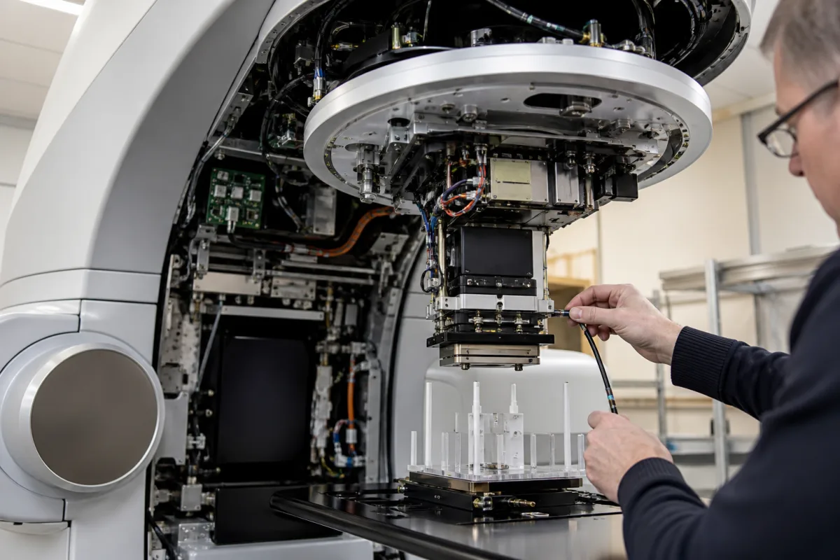
Linac beam monitoring system: the treatment-head monitor ionization chamber, its primary and backup channels, sealing and dose-rate feedback
The dual-channel transmission ionization chamber inside a linac treatment head · primary and backup monitor units, a 10 MU or 23 MU backup stop, sealed chambers that lose pressure, closed-loop dose-rate servo, 320 V polarizing voltage and recombination at FLASH dose per pulse
Every clinical electron linac carries an ionization chamber in the treatment head, below the flattening filter or scattering foil and above the jaws, through which the whole beam passes. It collects the charge the beam produces, converts it to monitor units, and terminates the irradiation when the prescribed number is reached; a second, independent channel stands by to stop the beam if the first fails. Buying, commissioning or servicing one comes down to how the two channels are compared and interlocked, whether the chamber is sealed or open to the air, and how its signal behaves when the collimators scatter radiation back into it or the dose per pulse rises far above the clinical range.
Beam (dose) monitoring systems built into medical electron linear accelerators: the transmission monitor ionization chamber in the treatment head, its primary and secondary (backup) dosimetry channels, electrometer and termination interlock, sealed and air-communicating chamber designs, dose-rate feedback to the electron gun, backscatter from collimators into the chamber, and ion recombination at high dose per pulse. Two-dimensional ionization chamber arrays placed on the couch for patient-plan and machine quality assurance are covered on the Ionization chamber arrays page; the complete machine on the Medical linear accelerator page; the treatment console and its interlock display on the Centralized control system page; the injector whose beam current the dose-rate servo adjusts on the Electron gun for a medical linear accelerator page; and the leaves that scatter radiation back toward the chamber on the Multi-leaf collimator page. Beam monitors in proton and ion therapy nozzles, and radiation shielding of X-ray inspection cabinets, are outside this page.
CNFX editorial research · Sources checked October 13, 2026 · 4 sources
MU1 and MU2: how the backup channel stops a 2,000 MU arc
Two monitor channels count the same beam. On the Elekta Infinity studied at the Cancer Hospital of the Chinese Academy of Medical Sciences in Shenzhen, the primary reading MU1 is the prescribed dose and the backup reading MU2 is compared with it; the Elekta manual, as cited by the authors, says the absolute difference should not exceed 10 MU, and Varian systems, with a different backup design and stopping mechanism, allow up to 23 MU before an error. [1] AAPM TG-142 sets a 2 % tolerance for backup monitor chamber constancy in both conventional treatment and SBRT. [1]
The five SBRT plans in that study ran arcs of 690–2,010 MU. [1] The backup channel halted the beam only when MU2 ran ahead of MU1; with MU2 set 1.5 % below MU1 every arc finished even at a 27.8 MU difference, which the authors reject because a failed primary channel would then be caught late. [1] Gantry angle shifted MU2 by up to 0.2 % against 0°, and field sizes from 2 × 2 to 30 × 30 cm had no observable effect. [1]
Editorial calculation: TG-142's 2 % of a 2,000 MU arc is 40 MU, four times the 10 MU stop cited for the Elekta machine; a 10 MU limit on that arc corresponds to 0.5 %, which matches the setting at which 6 MV arcs with high MU still stopped in the study.
Ask how the backup channel is compared with the primary (absolute MU or percentage), what limit stops the beam, whether a negative offset is possible, and how both channels are checked at the MU per arc your SBRT plans use.
02
Sealed or air-communicating chamber: pressure, Kapton windows and output drift
Monitor chambers are either sealed, holding a nominally constant mass of gas, or open to the atmosphere so that their response follows air temperature and pressure; the TrueBeam uses sealed chambers so that monitor readings need no atmospheric correction. [2] At the University of Wisconsin a TrueBeam STx showed daily output variations of up to ±2 %, with the standard deviation of daily dose per MU rising from 0.36 % to 0.84 %; once the chamber leaked, output followed the temperature-pressure correction with a slope of 0.84 (R² = 0.89). [2]
The physicists confirmed the leak by heating and then cooling the chamber over five hours: corrected readings departed from what a sealed chamber would give by up to 4.6 % but matched an air-communicating chamber within 1.3 % (k = 2). The removed chamber had a concave film surface, the sign of depressurisation. [2] After replacement, output rose by 0.6 % per month, which the authors attribute to sealed chambers slowly losing sensitivity as radiation-induced reactions of oxygen with the Kapton windows depressurise them; they cite about 1 % per 10⁵ monitor units reported by the manufacturer. [2]
Applied retrospectively, average-and-range control charts of daily output showed non-random variation from 6 November 2017, more than six weeks before the date the temperature-pressure trend had suggested, and the authors conclude the chamber was probably communicating with the atmosphere by then. [2] Editorial calculation: 0.6 % per month adds up to about 7 % over twelve months without recalibration; the Wisconsin output record after the exchange includes two calibration events. [2]
Ask whether the chamber is sealed or vented, the expected sensitivity drift per 10⁵ MU, the replacement interval, and what daily output check and control limits the supplier recommends to catch a leaking seal.
03
Closed-loop dose-rate servo, collimator backscatter and 320 V at FLASH dose per pulse
In the treatment head the flattened X-ray beam passes through the dose monitor chamber before the jaws; on a Siemens Primus studied in Hyderabad the upper and lower jaws sit about 22.47 cm and 30.27 cm from the beam monitor chamber, a xenon-filled chamber with a ceramic-metal coating on its exit window. [3] In closed-loop mode the ionization current from that chamber regulates the electron beam current and photon output, so radiation scattered back from collimators into the chamber lowers the output. [3]
With an add-on micro-MLC 56 cm from the target, the Hyderabad group measured at most 0.5 % less dose from backscatter into the monitor chamber at 6 MV, and up to 2.5 % difference in monitor unit rate between open and closed feedback loops. [3] They cite earlier work in which an aluminium exit window on a Clinac 1800 absorbed backscattered photons. [3]
At Lund University an Elekta Precise modified for ultra-high dose rate electron beams was used to test one of its two monitor chamber channels: at the standard negative polarizing voltage of 320 V, ion-collection efficiency was 0.1 at 0.98 Gy per pulse, and raising the voltage to 640 V and 960 V increased it by factors of 1.4 and 2.2. [4] The authors state that built-in transmission chambers, as implemented in conventional linacs, cannot be used for FLASH beams; with the voltage raised and a recombination model fitted, they used the chamber for real-time dosimetry, after calibrating it against a traceable dosimeter at conventional dose rates. [4]
Ask whether dose-rate feedback is taken from the monitor chamber, what backscatter correction applies with add-on collimators, the chamber polarizing voltage, and the highest dose per pulse at which the supplier states the monitor response is linear.
04
Data for a linac beam monitoring system
Paste it into your enquiry below or into an email to a maker, then replace every bracket.
Linac: [model; photon and electron energies; FFF or flattened]
Chamber: [sealed or vented; gas; window material; segments for flatness and symmetry]
Channels: [primary and backup; comparison rule; stop limit in MU or %]
Dose rate: [maximum MU/min; dose per pulse; servo to gun current]
Electronics: [polarizing voltage; electrometer range; interlocks]
Service: [expected drift per 10⁵ MU; replacement interval; recalibration after exchange]
Use: [largest MU per arc; SBRT or FLASH work]
Explore company information and manufacturing capabilities, then discuss the scope of your project with a relevant supplier.
Share this page
Compiled and source-reviewed by the CNFX editorial team.
Each manufacturer above links to the page on that company's own website where the product is listed, with the date we checked it. How we source and review
· Page last updated 13 October 2026
Buyer questions
What does the backup monitor chamber channel do?
It counts the same beam as the primary channel and halts delivery if its reading runs ahead of the primary by more than a set limit; on the Elekta Infinity studied in Shenzhen the stop is 10 MU, and Varian systems allow up to 23 MU. [1]
Why can a sealed monitor chamber cause output drift?
A leaking sealed chamber begins to follow air temperature and pressure; on a TrueBeam STx this produced daily output variations of up to ±2 % until the chamber was replaced. [2]
Does collimator backscatter affect the monitor chamber?
Yes. With dose-rate feedback active, backscatter into the chamber lowers the output; a micro-MLC on a Siemens Primus reduced 6 MV dose by at most 0.5 %. [3]
Can the built-in monitor chamber measure FLASH beams?
Only with a recombination correction: at 320 V the ion-collection efficiency of an Elekta Precise monitor chamber fell to 0.1 at 0.98 Gy per pulse. [4]
Sources and what still needs a direct check
Sources checked 2026-10-13. Four peer-reviewed clinical physics papers, each measuring the built-in monitor chamber of a different linac: an Elekta Infinity in Shenzhen, a Varian TrueBeam STx in Wisconsin, a Siemens Primus in Hyderabad and an Elekta Precise in Lund.