Editorial Technical Reference

Calibration System

This page explains how Calibration System is classified within Computer, Electronic and Optical Product Manufacturing. Technical values and manufacturer relationships are research references; confirm the current specification and supplier evidence for each order.

Technical Definition & Core Assembly

A subsystem within the Beam Monitoring System responsible for ensuring measurement accuracy and consistency of beam parameters.
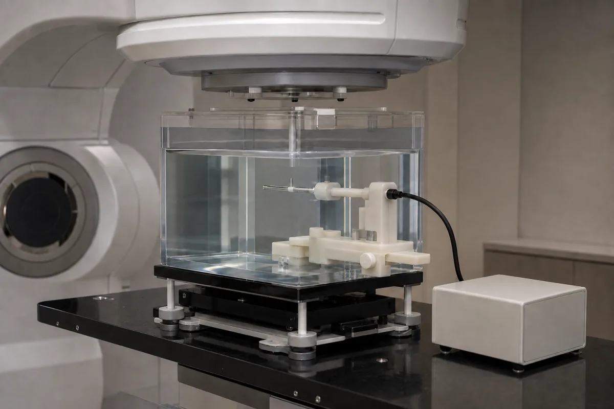
Representative product image. Confirm appearance and specifications with the manufacturer.

Product Specifications

Technical details and manufacturing context for Calibration System

Definition
The Calibration System is a critical component of the Beam Monitoring System that performs regular verification and adjustment of sensors and measurement devices to maintain precise monitoring of beam characteristics such as intensity, position, and profile. It ensures all monitoring equipment operates within specified tolerances through automated or manual calibration procedures. The system is designed for use in computer, electronic, and optical product manufacturing environments where beam monitoring is essential. It is a component-level product, typically integrated into a larger monitoring setup. The system's calibration accuracy is ±0.1% (ISO 5725-1), with a measurement range of 0.1–100 kW. Repeatability is ±0.05% (ISO 5725-1), and response time is ≤10 ms. It operates within a temperature range of 15–35 °C (IEC 60721-3-1) and can be stored at -20–60 °C. Relative humidity should be 20–80% RH (non-condensing). Power supply is 24 V DC ±10%, with power consumption ≤15 W. Communication interfaces include RS-485 and Ethernet (Modbus RTU/TCP, IEC 61158). The enclosure is rated IP54 (IEC 60529). Weight is ≤5 kg, and dimensions are 200×150×80 mm (without connectors). Materials include aluminum alloy, stainless steel, and electronic components. The system is designed for automated or manual calibration, comparing sensor readings against reference standards and applying correction factors. It is important to verify model-specific values and standards with the legal manufacturer or supplier, as the listed parameters are typical reference ranges. The system is not a standalone product but a component of a larger monitoring system, and its performance must be validated in the context of the specific application.
Working Principle
The system operates by comparing sensor readings against known reference standards or signals, then applying correction factors to eliminate measurement drift and errors. It typically involves generating controlled test signals, measuring system response, and adjusting calibration coefficients to align measurements with reference values. The calibration process can be automated or manual, depending on the configuration. The system uses reference standards to ensure traceability and accuracy. It monitors beam intensity, position, and profile, and adjusts sensors to maintain accuracy within specified tolerances. The system includes interfaces for communication and control, allowing integration with external monitoring systems. It is designed to operate within specified environmental conditions and power supply ranges. The calibration procedure should be performed regularly to maintain measurement accuracy and consistency.
Common Materials
Aluminum alloy, Stainless steel, Electronic components
Technical Parameters
ParameterTypical rangeNotes & selection driver
Calibration Accuracy±0.1 %Overall system accuracy including reference standardsISO 5725-1
Measurement Range0.1–100 kWCovers typical beam power range
Repeatability±0.05 %Maximum deviation between consecutive calibrationsISO 5725-1
Response Time≤10 msTime to reach 90% of final reading
Operating Temperature15–35 °COutside this range, accuracy may degradeIEC 60721-3-1
Storage Temperature-20–60 °CNon-operating conditionIEC 60721-3-1
Relative Humidity20–80 % RHNon-condensingIEC 60721-3-1
Power Supply24 ±10% V DCProtected against reverse polarity
Power Consumption≤15 WTypical value
Communication InterfaceRS-485, EthernetModbus RTU/TCP protocolIEC 61158
Ingress ProtectionIP54Dust and splash water protectedIEC 60529
Weight≤5 kgIncluding mounting bracket
Dimensions (L×W×H)200×150×80 mmWithout connectors

Ranges are indicative industry figures for RFQ preparation, not a supplier commitment. Confirm every value and standard with the legal manufacturer before ordering.

Components / BOM
  • Reference Signal Generator
    Produces precise, stable signals for calibration comparison
    Material: Electronic components, Aluminum housing
  • Calibration Controller
    Manages calibration sequences and stores correction coefficients
    Material: Circuit board, Plastic casing
  • Positioning Mechanism
    Adjusts calibration targets to precise locations relative to beam path
    Material: Stainless steel, Stepper motors
  • Communication and Control Interface
    Carries calibration commands in and results out to the beam monitoring system.

Applied To / Applications

This component is essential for the following industrial systems and equipment:

Industrial Ecosystem & Supply Chain Structure

Complementary Systems
Downstream Applications
Specialized Tooling

Application Fit & Sizing Matrix

Operational Limits
pressure: 0 to 2 bar absolute
flow rate: 0.1 to 10 L/min
temperature: -10°C to +50°C
slurry concentration: 0 to 20% solids by weight
Media Compatibility
✓ deionized water ✓ nitrogen gas ✓ non-corrosive process fluids
Unsuitable: highly abrasive slurries with >20% solids concentration
Sizing Data Required
  • beam energy range (eV to MeV)
  • required measurement accuracy (±%)
  • maximum beam current (A)

Reliability & Engineering Risk Analysis

Failure Mode & Root Cause
Drift
Cause: Environmental factors (temperature, humidity), component aging, or mechanical stress altering sensor/instrument baseline accuracy over time.
Hysteresis
Cause: Mechanical wear, friction, or material memory effects causing inconsistent readings between increasing and decreasing measurement cycles.
Maintenance Indicators
  • Out-of-tolerance readings during routine verification checks
  • Inconsistent or erratic measurement outputs under stable conditions
Engineering Tips
  • Implement environmental controls (stable temperature/humidity) and regular calibration schedules based on usage intensity and manufacturer recommendations
  • Use certified reference standards, proper handling procedures, and document calibration history to track performance trends and predict failures

Indicative industry ranges for design and RFQ preparation. Confirm the exact figures and applicable standard with the manufacturer before specifying.

Compliance & Manufacturing Standards

Applicable Standards
ANSI/NCSL Z540.3 Calibration Laboratories

Quoted from the published standard.

Manufacturing Precision
  • Measurement Uncertainty: +/-0.01% of reading
  • Repeatability: 0.005% of full scale
Quality Inspection
  • Traceability Verification to National Standards
  • Environmental Condition Monitoring (Temperature, Humidity, Pressure)

Manufacturers of Calibration System

2 companies list this product among what they make. Company figures are quoted from each company's own website; every card states where the relationship came from.

Useon Technology Limited
Zhenjiang (Jurong factory), Jiangsu, CN
Listed on the company's own website · profile compiled by CNFX from public sources
Xi'an Yunyi Instrument Co., Ltd.
Shaanxi, CN
Listed on the company's own website · profile compiled by CNFX from public sources

Manufacturer listings support early research and capability understanding. They are not certification, ranking, or transaction guarantees.

Technical documentation
Request current drawings, revision history, and a signed specification sheet.
Manufacturing capability
Verify equipment lists, process limits, capacity, and representative production evidence.
Inspection readiness
Confirm test methods, calibrated equipment, sampling plans, and traceable reports.
Supplier transparency
Check the legal entity, factory address, ownership, certifications, and direct contacts.

CNFX does not score or rank suppliers. Buyers must verify all claims and documents with the legal manufacturer before ordering.

Supply Chain Compatible Machinery & Devices

Industrial IoT Gateway

The Industrial IoT Gateway is a ruggedized edge computing device designed for industrial environments.

Explore Specs →
Modular Industrial Edge Computing Device

This modular industrial edge computing device is a ruggedized system designed for deployment in harsh industrial environments to perform real-time data processing, analytics, and control functions at the network edge.

Explore Specs →
Industrial Smart Camera Module

The Industrial Smart Camera Module is a compact, self-contained vision processing unit designed for integration into industrial machinery and production lines.

Explore Specs →
Surface Mount Resistor

Passive electronic component for current limiting and voltage division in circuits

Explore Specs →

Frequently Asked Questions

What is the calibration accuracy of the Calibration System?

The calibration accuracy is ±0.1% as per ISO 5725-1. This is a reference value; verify the specific model's accuracy with the manufacturer.

What is the measurement range of the system?

The measurement range is 0.1–100 kW, covering typical beam power. Confirm the exact range for your application with the supplier.

What communication interfaces are available?

The system supports RS-485 and Ethernet with Modbus RTU/TCP protocol, per IEC 61158. Check the specific model for available interfaces.

What are the environmental operating conditions?

Operating temperature is 15–35 °C, storage -20–60 °C, and relative humidity 20–80% RH (non-condensing), per IEC 60721-3-1. Ensure the environment meets these conditions.

Data Basis

Editorial classification, named public sources where available, and source-reviewed manufacturer records.

Preliminary Technical Classification
This page supports structured research, RFQ preparation, and supplier evaluation. It does not replace buyer-led supplier qualification, standards review, or technical approval.
Buyer enquiry

Request manufacturing insight for Calibration System

Ask for use case, specification boundaries, supplier type, and RFQ preparation information for this product.

Where it goes
Straight to the CNFX editorial desk, and to the manufacturer if this product is linked to a claimed profile. Nothing is broadcast to a supplier list.
Your details stay here
We do not sell or rent enquiry data, and we do not add you to a mailing list. Used only to answer this request.
No commission, no middleman
CNFX is a directory. We take no cut of any order and never negotiate on a supplier's behalf.
What we don't claim
A listing is not an endorsement. Qualify every supplier and verify every figure yourself before ordering.

Your business information is used only to process this request.

Thank you! Your message has been sent. We'll respond within 1–3 business days.
Sorry, we couldn't send your message. Please try again, or email us at contact@cnfx.com.

Need to Manufacture Calibration System?

Compare manufacturer profiles with relevant product and process capability.

Previous Product
Bus Interface Unit
Next Product
Cavity Body
Get QuotesChat