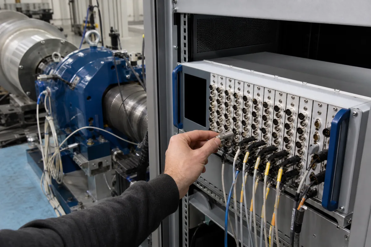
Analog input modules · Sampling rate and anti-alias filtering, simultaneous versus multiplexed sampling, Modbus RTU timing
A data acquisition module takes analog signals from sensors or transmitters, conditions them, converts them to numbers and passes them to a controller or computer, either as a card in a measurement chassis or as a DIN-rail module on a fieldbus such as Modbus RTU over RS-485. Ask three things first: whether its sampling rate and anti-alias filtering suit the highest frequency in your signal, whether its channels are sampled simultaneously or one after another, and how fast its interface can deliver the readings.
Analog input data acquisition modules: chassis-based DAQ cards and remote I/O or DIN-rail acquisition modules with serial or fieldbus interfaces. Stand-alone data loggers, converter chips, sensors and transmitters, and complete test benches are outside this page.
CNFX editorial research · Sources checked October 12, 2026 · 4 sources
Set the sampling rate against the anti-alias filter
Dataforth's application note states that the sample rate must exceed twice the highest frequency applied to the converter to avoid aliasing, and that all frequencies above half the sample rate must be attenuated below the level the ADC can detect. Its example: with an 8-pole Bessel filter whose corner f1 is 1 kHz and a 12-bit ADC, whose sensitivity is about −72 dB, frequencies up to about 6 kHz can still be detected, so the minimum sample rate is 2 × 6 kHz = 12 kHz, not 2 kHz. [1]
The note adds that digital filters can never replace the analog anti-alias filter, because aliasing occurs in the converter. Bessel filters have linear phase and suit pulses and time-domain work, but have pass-band gain error near f1; elliptic filters reject the stop band fastest but distort waveforms in time. Sampling to the Nyquist rule preserves frequency content, while recording meaningful time-domain shape needs higher rates still. [1]
Editorial calculation: 12 bits give 4,096 steps, and 20 × log10(1/4096) ≈ −72 dB, matching Dataforth's figure; a 16-bit module on a ±10 V range resolves 20 V/65,536 ≈ 305 µV per step. [1]
Give the supplier the signal types and ranges, number of channels, highest signal frequency and required sample rate per channel, whether channels must be sampled simultaneously, anti-alias filter needs, accuracy, isolation (channel-to-channel and to bus), interface and protocol, update rate required by the controller, supply voltage, mounting, environment and hazardous-area approvals.
02
Check whether channels are sampled simultaneously
Beckhoff describes two sampling types. In simultaneous sampling each channel has its own converter, triggered together, so all values belong to the same instant; in multiplex sampling one converter is switched from channel to channel in the microsecond range, which is cheaper but means the values are acquired one after another. Beckhoff recommends simultaneous designs for time-demanding tasks. [2]
To check an unknown device, Beckhoff suggests applying the same test signal to all channels and looking for an offset between them: "the easiest test to perform is with a square wave signal because an offset can then be easily observed", and with a sine wave, concentrate on the zero crossing because amplitude differences appear as time offset. A single-channel device is simultaneous by definition. [2]
Editorial note: for vibration, power or any phase comparison between channels, ask the supplier for the channel-to-channel skew, or confirm simultaneous sampling in the data sheet; for slow temperature or level signals, multiplexed modules can be adequate.
03
Check how fast the interface can deliver readings
The Modbus over serial line specification allows up to 247 slave addresses on one bus, a maximum RTU frame of 256 bytes, 11 bits per RTU character with even parity as the required default, and frames separated by at least 3.5 character times; a gap of more than 1.5 character times inside a frame marks it incomplete. Above 19,200 bps it recommends fixed timers of 750 µs (t1.5) and 1.750 ms (t3.5). [3]
It requires 9,600 bps and 19.2 kbps with 19.2 kbps as the default, gives a maximum trunk length of 1,000 m at up to 9,600 baud with AWG26 or wider cable, calls for a line termination such as a 150 Ω (0.5 W) resistor near each end, and notes that more than 32 devices need a repeater. It states that "typically the Response time-out is from 1s to several second at 9600 bps; and the Turnaround delay is from 100 ms to 200ms". [3]
Editorial calculation: at 9,600 bps one 11-bit character takes 1.15 ms, so t3.5 ≈ 4.0 ms and a full 256-byte frame ≈ 293 ms. Serial polling of this kind suits slowly changing process values rather than waveform capture at kS/s. [3]
04
RS-485 acquisition and remote I/O modules, with the ADAM-4017+ as a worked example
Both suppliers reviewed list industrial acquisition and remote I/O modules rather than high-speed chassis systems; ask each for sampling rate per channel, sampling type, filtering, isolation and protocol.
A published example of the DIN-rail serial type is Advantech's ADAM-4017+, an 8-channel analog input module on RS-485 with Modbus/RTU and ASCII command protocols. Advantech lists input ranges of ±150 mV, ±500 mV, ±1 V, ±5 V and ±10 V, 0–150 mV to 0–10 V, and 0–20 mA, 4–20 mA and ±20 mA; 16-bit resolution; a sampling rate of 10 S/s as a sum for the module; 3,000 V DC isolation; a watchdog timer; 10–30 V DC supply; −10 to 70 °C operation; and two 10-pin plug-in screw terminals. [4] Editorial calculation: 10 S/s shared by 8 channels is 1.25 S/s per channel when all are scanned, so by Dataforth's sampling rule the content of each signal must stay below about 0.6 Hz — suitable for temperature, level or pressure trends, not for vibration; on ±10 V, 16 bits give the 305 µV step calculated above. [4][1]
05
Terminals, anti-alias filter, multiplexer, ADC, isolation and bus interface
Block
Role
Fix in the order
Input terminals and conditioning
Scale and protect the signal.
Ranges; sensor types.
Anti-alias low-pass filter
Removes frequencies above half the sample rate. [1]
Channels, per-channel sample rate, resolution, isolation and protocol for a DAQ module order
Write the sampling rate per channel, not per module: the ADAM-4017+'s 10 S/s is shared by eight inputs, which is the difference between a temperature trend and a usable vibration record.
Field
What it means and published values
Ask the supplier for
Number of Input Channels (channels)
Simultaneous or multiplexed; e.g. 8 channels sharing 10 S/s on one serial module. [2][4]
2 companies list this product among what they make. Company figures are quoted from each
company's own website; every card states where the relationship came from.
Beijing Pinghe Entrepreneurship Technology Development Co., Ltd.
Manufacturing site to be confirmed for the order
Lists data acquisition modules with isolated I/O modules, remote I/O and safety barriers.
Explore company information and manufacturing capabilities, then discuss the scope of your project with a relevant supplier.
Share this page
Compiled and source-reviewed by the CNFX editorial team.
Each manufacturer above links to the page on that company's own website where the product is listed, with the date we checked it. How we source and review
· Page last updated 13 October 2026
Buyer questions
How fast must a data acquisition module sample?
Faster than twice the highest frequency the converter can still detect; Dataforth's 12-bit example with a 1 kHz 8-pole Bessel filter needs 12 kHz. [1]
What is the difference between simultaneous and multiplexed sampling?
Simultaneous modules sample all channels at the same instant with separate converters; multiplexed modules switch one converter across channels in turn. [2]
What limits Modbus RTU data acquisition speed?
Serial timing: 11-bit characters, 3.5-character gaps between frames and up to 256-byte frames, at 19,200 bps by default or 9,600 bps. [3]
Is a 10 S/s module's rate per channel or for the whole module?
Check the data sheet wording: Advantech lists the ADAM-4017+ at 10 S/s as a sum, so with all 8 channels enabled each channel is read about 1.25 times per second. [4]
Sources and what still needs a direct check
Sources checked 2026-10-12. Dataforth, Beckhoff and Advantech are module makers explaining sampling or listing their own module data; the Modbus serial line specification is published by Modbus.org. Module figures must come from its own data sheet.