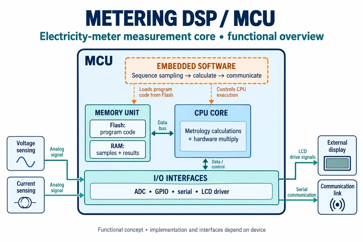
DSP/MCU measurement core for electricity metering: the mixed-signal microcontroller that samples voltage and current and computes energy
Metrology microcontrollers · Mixed-signal MCUs with sigma-delta ADCs and multiply hardware that form the measurement core of electricity meters and embedded sub-meters
In an electricity meter or an embedded sub-meter, the measurement core is the chip that turns shunt or current-transformer signals and a divided-down mains voltage into watt-hours. A metering microcontroller does this on one die: sigma-delta converters sample each channel, a CPU with hardware multiply runs the metrology (DSP) routines, and the same chip keeps the clock, drives the display and talks to the communication module. The questions for a design are whether the converters' input range and dynamic range cover the meter's current span, which accuracy class the finished meter must meet, and how the chip keeps time and data through supply loss.
Mixed-signal microcontrollers with integrated sigma-delta ADCs and metrology firmware support used as the measurement core of single-phase, poly-phase and embedded electricity meters, and the accuracy-class requirements they serve. General-purpose DSP chips and cores are covered on the Digital signal processor (DSP chip) page, general microcontrollers on the Microcontrollers (CPU / MCU) page, battery-logger MCUs on the Low-power microcontroller page, and stand-alone measurement front ends without a CPU on the Analog front-end (AFE) IC page. Complete meters are outside this page.
CNFX editorial research · Sources checked October 17, 2026 · 3 sources
Sigma-delta channels, PGA gain and the shunt they can read
TI's MSP430i204x has four 24-bit sigma-delta ADCs with differential PGA inputs (the i203x three, the i202x two), a hardware multiplier for 16-bit operations, a 16.384 MHz internal DCO and a 2.2 V to 3.6 V supply. With the internal reference (1.158 V, typ.), the differential input range for specified performance is ±928 mV at gain 1, ±464 mV at gain 2, ±232 mV at gain 4, ±116 mV at gain 8 and ±58 mV at gain 16. [1]
At an oversampling ratio of 256 and 50 Hz input, the datasheet gives SINAD of 89 dB (typ.) at gain 1 falling to 77 dB (typ.) at gain 16, integral nonlinearity of ±0.003 % FSR, gain error within ±2 %, a gain-error temperature coefficient of 50 ppm/°C (typ.) and 190 µA (typ.) per converter at gains 1 to 16. TI notes that the external digital clock in DCO bypass mode must be 16.384 MHz for the converter to meet its specified performance. [1]
Editorial calculation: to keep a 60 A rms current within the ±58 mV range at gain 16, the shunt must satisfy 60 A × √2 × R ≤ 58 mV, so R ≤ 58 mV / 84.9 A ≈ 0.68 mΩ. At 60 A rms that shunt dissipates 60² × 0.00068 ≈ 2.4 W. The 60 A maximum current is assumed for illustration; the ±2 % gain error is removed by calibration, not by shunt choice. [1]
Give the chip supplier the sensor type and value for each current channel, the voltage divider ratio, the meter's Imax and starting current, and the calibration method used in production.
02
What else the chip carries for a meter: display, clock and auxiliary supplies
TI's MSP430F673x is aimed at 2-wire and 3-wire single-phase metering and tamper-resistant meters. It combines up to three 24-bit sigma-delta ADCs with differential PGA inputs, a 10-bit 200 ksps ADC, a 32-bit hardware multiplier, an LCD driver for up to 320 segments in 8-mux mode, a password-protected RTC with crystal offset calibration, a 3-channel DMA, and a power system that can run from up to two auxiliary supplies, at up to 25 MHz system clock and 1.8 V to 3.6 V. [2]
Its datasheet lists 1.7 µA at 2.2 V and 2.5 µA at 3.0 V (typ.) in standby with RTC, watchdog and supply supervisor running and full RAM retention, and 1.24 µA (typ.) in shutdown with the RTC active. [2] For a meter, those figures size the backup battery or supercapacitor that keeps time and tariff registers through a mains outage.
03
Accuracy classes A to D and the current range the measurement core must cover
OIML R 46 (2012) for active electrical energy meters assigns each meter one of four accuracy classes. For direct-connected meters it requires Imax/Itr ≥ 50 in every class, Imax/Imin ≥ 100, 125, 250 and 250 for classes A, B, C and D, and Imax/Ist ≥ 1,000 for class A and ≥ 1,250 for B, C and D. Between Itr and Imax at unity power factor the base maximum permissible errors are ±2.0 %, ±1.0 %, ±0.5 % and ±0.2 % for classes A to D. [3]
Editorial calculation: for an assumed class C direct-connected meter with Imax = 60 A, Imin must be no more than 60 / 250 = 0.24 A and Ist no more than 60 / 1,250 = 48 mA. With the 0.68 mΩ shunt above, 48 mA produces about 33 µV, which the converter and firmware must still turn into registered energy. [3][1]
R 46 also limits the temperature coefficient of error between Itr and Imax at unity power factor to ±0.1, ±0.05, ±0.03 and ±0.01 %/K for classes A to D, the class D values doubling below −10 °C. [3] The chip's own gain drift, given by TI as 50 ppm/°C (typ.), or 0.005 %/K, therefore takes a measurable share of a class C or D budget before the shunt and voltage divider are counted. [1]
04
Meter data to give the chip and firmware supplier
Paste it into your enquiry below or into an email to a maker, then replace every bracket.
Meter: [single- or poly-phase; direct or transformer-operated; accuracy class]
Currents: [Imax; Itr; Imin; Ist]
Sensors: [shunt value or CT ratio per channel; voltage divider]
Functions: [registers; tariffs; RTC accuracy; display; tamper detection]
Supply: [backup battery or supercap; auxiliary supply]
Production: [calibration method; test points]
Explore company information and manufacturing capabilities, then discuss the scope of your project with a relevant supplier.
Share this page
Compiled and source-reviewed by the CNFX editorial team.
Each manufacturer above links to the page on that company's own website where the product is listed, with the date we checked it. How we source and review
· Page last updated 17 October 2026
Buyer questions
What input range does a metering sigma-delta ADC accept?
TI's MSP430i2041 accepts ±928 mV differential at gain 1 down to ±58 mV at gain 16 with its internal reference. [1]
What error must a class C electricity meter meet?
OIML R 46 sets a base maximum permissible error of ±0.5 % between Itr and Imax at unity power factor for class C. [3]
Sources and what still needs a direct check
Sources checked 2026-10-17. Two Texas Instruments datasheets (SLAS887C, March 2021; SLAS731D, September 2018) supply the chip figures; the meter requirements come from OIML R 46-1/-2, Edition 2012, the International Recommendation for active electrical energy meters.