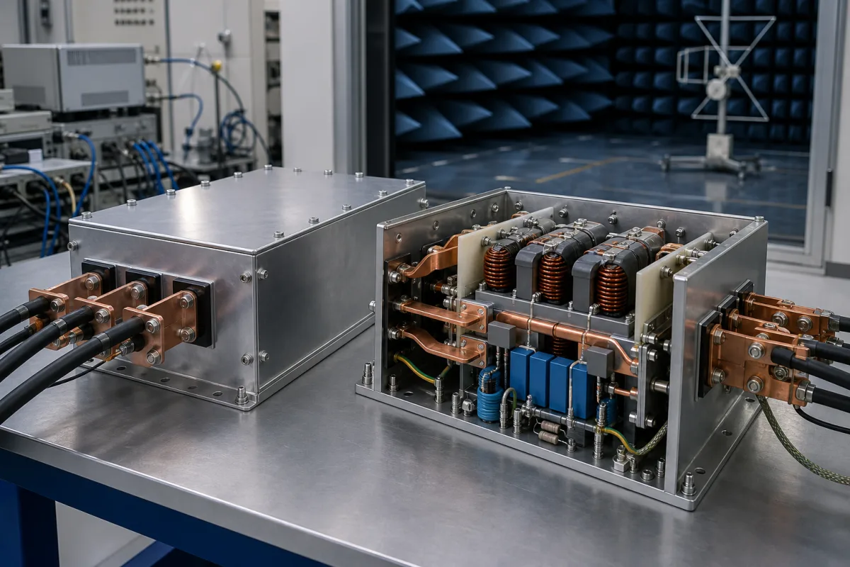
Power-line EMC · Rated current and temperature, leakage current, test voltage, attenuation and overload
Start with the mains configuration and the load current at cabinet temperature. Leakage and attenuation then need their own test conditions: a current rating alone cannot establish compatibility with the drive, cables or residual-current protection.
Single-phase and three-phase power-line EMI filters for drives, power supplies and equipment, including chassis, DIN-rail and IEC-inlet types. Board-level EMI suppression components, RF and phase-noise filters, sine-wave and harmonic filters, and shielded rooms are outside this page.
CNFX editorial research · Sources checked October 18, 2026 · 4 sources
Read a three-phase EMI filter datasheet: a worked example
LinMot’s NF01-FN258-16-07 datasheet lists a maximum continuous voltage of 480 VAC at 50 °C and a current rating of 16 A at 50 °C, or 17.5 A at 40 °C. Its 7.5 kW typical-drive example is calculated at rated current, 440 VAC and cos φ = 0.8; the footnote also identifies drive, motor and application efficiency. It is not a general power-to-filter selection rule. [1]
The same sheet specifies a 2-second high-potential test of 2,650 VDC phase-to-earth and 2,100 VDC phase-to-phase. These are DC test voltages, not continuous operating voltages or AC withstand ratings. IP20, 20 W loss at 25 °C/50 Hz and a −25 to +100 °C operation/storage range are separate entries; the temperature range does not promise full rated current at 100 °C. [1]
Its overload entries are four times rated current at switch-on, without a stated duration there, and 1.5 times rated current for one minute once per hour. Obtain the permitted startup duration and repetition for the selected variant. The sheet’s statements about design standards do not independently verify certification of an ordered assembly. [1]
Editorial arithmetic: 17.5/16 = 1.09375, so the tabulated 40 °C current is 9.375% higher than the 50 °C value for this variant. Those two points do not establish a universal derating factor or permission to interpolate over the entire temperature range. [1]
The attenuation plot labels four impedance conditions: 50 Ω/50 Ω symmetrical and asymmetrical, 0.1 Ω/100 Ω symmetrical, and 100 Ω/0.1 Ω symmetrical. Compare the same mode, frequency and source/load impedances. A catalogue curve alone does not establish the emissions of the assembled equipment. [1]
State supply voltage, phase and neutral arrangement, load current and overload timing, cabinet temperature, drive and cable configuration, attenuation test conditions, permitted leakage, mounting and terminal requirements.
02
Check leakage current, including fault cases
LinMot specifies 18.3 mA maximum leakage under normal operation at 440 VAC/50 Hz. Its footnote says leakage could reach 5.7 times higher levels if two phases are interrupted. This is a model-specific fault condition, not a normal rating. [1]
Editorial arithmetic: 18.3 × 5.7 = 104.31 mA for that stated worst-case factor. This does not establish measured fault leakage for another model or permission to operate with lost phases. Obtain normal and fault-case data at the actual supply voltage and frequency. [1]
DOREXS and WEMC list medical or low-leakage filter ranges. A category name does not establish medical-equipment compliance or compatibility with a particular protective device. Specify the complete application and obtain the relevant assembly documentation. [3][2]
03
Phase configuration and assembled-filter supply scope
WEMC’s catalogue distinguishes three-phase, single-phase and IEC-inlet assemblies. DOREXS separately lists single-phase, three-phase, IEC-inlet and medical ranges. Keep the phase/neutral arrangement, mounting and leakage variant attached to the actual order code. [2][3]
The reviewed offers below include assembled AC power-line filters. Board-mounted DC input modules, magnetic cores and current transformers are different supply items. A shielded-room power-line filter may fit this electrical scope; a complete shielded room does not.
04
Ask for a low-leakage version where RCDs protect the circuit
Schurter describes FMBC LL as a low-leakage, two-stage three-phase series suitable for applications with RCDs. Its sheet covers 7–180 A at 50 °C and 520 VAC, 50/60 Hz. Leakage is tabulated at 400 VAC/50 Hz according to IEC 60939-1: 4.3 mA for 7–55 A variants, 17.5 mA for 75/100 A and 19.3 mA for 130/180 A. The series description is not a universal RCD compatibility statement. [4]
The sheet lists 1.5 times rated current for one minute per hour and 2-second dielectric tests above 2.25 kVDC line-to-line and above 2.7 kVDC line-to-PE. Its −25 to +100 °C range is accompanied by derating information; use the selected variant’s permitted current at the actual temperature. [4]
The 16 A examples show 4.3 mA at 400 VAC for Schurter and 18.3 mA at 440 VAC for LinMot. These are different supply conditions, so the raw ratio is not a controlled comparison. Obtain data at a consistent voltage, frequency and test method. [4][1]
Review the complete installation with the equipment and protective-device suppliers: filter, drive, cables, supply arrangement, leakage waveforms, transients and fault cases all matter. Comparing an estimated steady leakage total with an RCD trip-current number alone does not establish compatibility. [4][1]
Chokes, line capacitors, earth branches and enclosure
LinMot’s schematic distinguishes coupled chokes, Cx capacitors between phase conductors and Cy branches toward earth. This functional breakdown covers the principal assembly parts; it is not a universal circuit or a production bill of materials. [1]
Part
Role
Fix in the order
Common-mode choke
Coupled windings form part of the interference attenuation network. [1]
Winding current, thermal conditions, topology and measured attenuation.
X capacitor / Cx branch
Connected between phase conductors in the illustrated circuit. [1]
Capacitance, voltage and appropriate component safety classification.
Y capacitor / Cy branch
Connects toward protective earth in the illustrated network and contributes to leakage. [1]
Leakage budget, capacitance and appropriate component safety classification.
Metal housing
Mechanical enclosure and mounting interface; the example assembly is IP20. [1]
Envelope, mounting points, protective bonding and environmental protection.
Terminals and leads
The example lists 6 mm² solid or 4 mm² flexible conductor and 0.6–0.8 N·m terminal torque. [1]
The selected terminal, conductor preparation, wire size and assembly instructions.
Insulation system
Separate phase-to-earth and phase-to-phase high-potential tests are specified. [1]
Test waveform, voltage, duration, conditions and applicable verification documents.
06
Continuous ratings, insulation tests and mounting envelope
Use the model’s stated units and test conditions. Continuous ratings, brief insulation tests, environmental qualification and physical dimensions describe different constraints.
Field
What it means and published values
Ask the supplier for
Rated voltage (V AC)
LinMot: 480 VAC at 50 °C; separate from its DC high-potential tests. [1]
Continuous supply rating and phase/neutral configuration.
The reviewed ranges include single-phase, three-phase and inlet-mounted assemblies. Match the phase/neutral arrangement, leakage variant, enclosure and terminals to a specific order code.
Chengdu Mengsheng Electronics Co., Ltd.
TBC
DOREXS lists single-phase, three-phase, IEC-inlet and medical power-line filter ranges. Obtain the actual order code and assembly documentation.
Lists MCT6TN and MCT6TN2 three-phase four-line EMI filter assemblies. Confirm the complete filter configuration separately from its magnetic-component range.
Lists single-phase, three-phase, IEC-inlet and medical EMI filter ranges. Confirm the phase configuration, housing and leakage variant of the selected assembly.
Lists EMI/RFI power-line filters as shielding accessories. Confirm the standalone electrical assembly, phase arrangement and test data rather than a complete shielded-room package.
Explore company information and manufacturing capabilities, then discuss the scope of your project with a relevant supplier.
Share this page
Compiled and source-reviewed by the CNFX editorial team.
Each manufacturer above links to the page on that company's own website where the product is listed, with the date we checked it. How we source and review
· Page last updated 13 October 2026
Buyer questions
Does a −25 to +100 °C range mean full rated current at 100 °C?
No. The LinMot sheet separately rates current at 50 °C and 40 °C. Obtain the permitted current and derating for the actual ambient and variant. [1]
Is the 2,650 V phase-to-earth figure an AC working voltage?
No. LinMot specifies a 2,650 VDC high-potential test for two seconds. Its continuous operating voltage is a separate 480 VAC entry at 50 °C. [1]
Can the normal and interrupted-phase leakage figures be interchanged?
No. The 18.3 mA value is at 440 VAC/50 Hz under normal operation; the possible 5.7-fold increase belongs to a stated two-phase interruption condition. [1]
Does the FMBC LL series description approve every RCD combination?
No. Use its model-specific leakage and rating data, then establish compatibility for the complete equipment and protective-device arrangement. [4]
Sources and what still needs a direct check
Sources checked 2026-10-18. LinMot’s two-page Edition 24 datasheet provides one drive-filter example. Schurter’s current seven-page PDF is marked 02.09.2025 and supplies a separate series comparison. WEMC and DOREXS establish offered product ranges; their category descriptions do not verify every assembly rating.