Flat panel X-ray detectors for digital radiography
Digital radiography flat panel detectors · Scintillator and DQE, pixel pitch and limiting resolution, IEC 62220-1 test data, US clearance
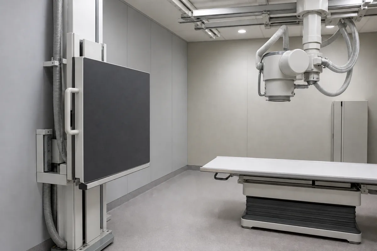
A flat panel detector converts X-rays into a digital image; the indirect designs reviewed here use a scintillator layer that turns X-rays into light over an amorphous silicon TFT sensor array, and replaces film or image plates in radiography rooms like the one pictured, mounted in a wall stand or used portably. Ask three things first: which scintillator it uses and what DQE it achieves, what pixel pitch and resolution it offers for your examinations, and what regulatory clearance and test reports support it in your market.
Indirect-conversion (scintillator on amorphous silicon TFT) flat panel detectors for general radiography, fixed and portable, wired and wireless. Mammography detectors, dental intraoral sensors, CT detectors and complete X-ray systems are outside this page.
CNFX editorial research · Sources checked October 12, 2026 · 4 sources
Rayence's FDA 510(k) summary for its 1417PCA portable detector describes a caesium iodide (CsI) scintillator directly coupled to an amorphous silicon TFT sensor, with 14 × 17 inch imaging area. It reports MTF, DQE and noise power spectrum (NPS) measured with the same equipment and the analysis method of IEC 62220-1, and a DQE of 55% at the lowest spatial frequency, against 52% for its CsI predicate. [1]
Rayence's 510(k) summary for its 910SGA detector, which uses a gadolinium oxysulfide (GOS) scintillator, reports a DQE of 46% at the lowest spatial frequency, against 45% for its predicate. Both summaries explain DQE as the detector's ability to show object details of a given size and contrast, its signal-to-noise transfer from input to output as a function of frequency. [2][1]
Editorial note: these are figures each maker reported for its own detectors at the lowest spatial frequency; compare detectors on DQE curves across frequency measured to IEC 62220-1 at the same beam quality, not on a single headline number.
Give the supplier the examinations and patient groups, fixed or portable use, the X-ray generator and its interface, required imaging area, pixel pitch and resolution, DQE and MTF data required, wired or wireless connection, battery needs, software and DICOM integration, and the regulatory clearance needed in your market.
02
Match pixel pitch to resolution and image size
The 1417PCA has a 127 µm pixel pitch, a 3328 × 2816 pixel matrix (9.4 million pixels) and 3.9 lp/mm resolution, against 150 µm, 2880 × 2400 pixels and 3.3 lp/mm for its predicate; both digitise at 14 bits (16,384 grey levels). Its total area is 422.7 × 357.6 mm, active area 416.6 × 351.8 mm, fill factor 65.14%, and weight 3.6 kg. [1]
Editorial calculation: the limiting resolution of a pixel grid is 1 ÷ (2 × pitch), so 127 µm gives 1 ÷ 0.254 mm ≈ 3.9 lp/mm and 150 µm gives about 3.3 lp/mm, matching the figures in the summary. [1]
Samsung's 510(k) summary for a detector added to its XGEO GU60A system notes that pixel pitch determines image resolution, that high-contrast limiting resolution rises as pitch falls, and lists differences in pixel pitch, limiting resolution, DQE, MTF and the addition of wireless communication as affecting image quality but not safety. [3]
03
Check the clearance and its scope
In the US these detectors are cleared as solid state X-ray imaging devices (product code MQB) under 21 CFR 892.1680, the regulation for stationary X-ray systems, which are Class II with special controls. The summaries reviewed state that the detectors are intended to replace film or screen-based radiography — the 1417PCA "in all general purpose diagnostic procedures" — and are "not to be used for mammography". [4][1][2]
The summaries also describe clinical images reviewed by a licensed US radiologist as part of showing substantial equivalence to the predicate device. [1] Editorial note: ask for the clearance number and indications for the exact model and configuration you are buying, as clearances apply to specific devices.
04
Wired and wireless detectors, and detectors sold with DR, C-arm and mammography systems
Listings include wired and wireless flat panel detectors, detectors offered with digital radiography, C-arm and mammography systems, and detectors among X-ray machine accessories. Ask each supplier for the scintillator, pixel pitch, DQE and MTF curves to IEC 62220-1, and the regulatory clearances for each model.
05
Scintillator, a-Si TFT array, readout and ADC, housing, communication and software
The scintillator row is where the two Rayence detectors differ: CsI in the 1417PCA at 55% DQE and GOS in the 910SGA at 46%, both at the lowest spatial frequency. [1][2]
Imaging area, pixel pitch, limiting resolution, bit depth and weight for a detector order
The published values come from the two Rayence 510(k) summaries; frame rate, kVp range, temperatures, humidity, IP rating and power have no published value here. [1][2]
4 companies list this product among what they make. Company figures are quoted from each
company's own website; every card states where the relationship came from.
Shenzhen SONTU Medical Imaging Equipment Co., Ltd.
Manufacturing site to be confirmed for the order
Lists wired and wireless flat panel detectors with digital radiography systems.
Explore company information and manufacturing capabilities, then discuss the scope of your project with a relevant supplier.
Share this page
Compiled and source-reviewed by the CNFX editorial team.
Each manufacturer above links to the page on that company's own website where the product is listed, with the date we checked it. How we source and review
· Page last updated 13 October 2026
Buyer questions
Is CsI better than GOS in a flat panel detector?
In Rayence's 510(k) summaries, its CsI detector reported 55% DQE and its GOS detector 46%, both at the lowest spatial frequency. [1][2]
How does pixel pitch relate to resolution?
A 127 µm pitch gives about 3.9 lp/mm and 150 µm about 3.3 lp/mm, as reported for Rayence's 1417PCA and its predicate. [1]
How are flat panel detectors regulated in the US?
They are cleared through 510(k) as solid state X-ray imaging devices under 21 CFR 892.1680, Class II. [4][1]
Sources and what still needs a direct check
Sources checked 2026-10-12. The 510(k) summaries are documents makers submitted to the US FDA describing their own detectors; 21 CFR 892.1680 is the US classification regulation.