Editorial Technical Reference

Photodiode Array

This page explains how Photodiode Array is classified within Computer, Electronic and Optical Product Manufacturing. Technical values and manufacturer relationships are research references; confirm the current specification and supplier evidence for each order.

Technical Definition & Core Assembly

A linear or two-dimensional arrangement of multiple photodiodes integrated on a single semiconductor substrate for simultaneous detection of light intensity across multiple points.
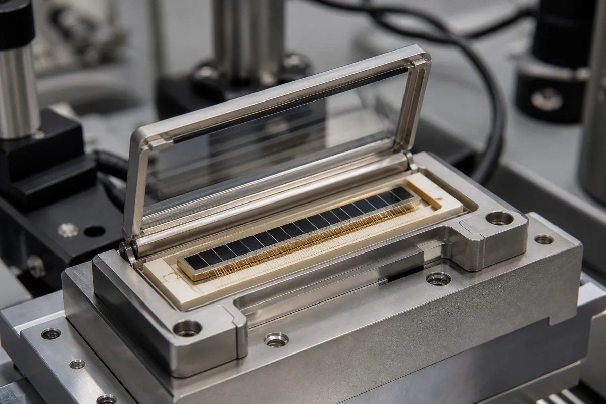
Representative product image. Confirm appearance and specifications with the manufacturer.

Product Specifications

Technical details and manufacturing context for Photodiode Array

Definition
A photodiode array is a key component within a Position-Sensitive Detector (PSD) system. It consists of multiple discrete photodiode elements arranged in a precise pattern (typically linear or matrix). In a PSD, the array captures incident light, and by analyzing the signal distribution across the individual diodes, the system can determine the position, movement, or profile of a light spot or image falling on its surface with high spatial resolution. The array is manufactured on a semiconductor substrate, with common materials including silicon (Si), germanium (Ge), and indium gallium arsenide (InGaAs), each offering different spectral response ranges. The pixel pitch, defined as the center-to-center spacing between adjacent photodiodes, is a critical parameter that determines the spatial resolution of the PSD; typical values are specified in millimeters (mm) and must be confirmed for the specific model. The array operates on the principle of the photoelectric effect in semiconductor p-n junctions: photons with energy exceeding the bandgap generate electron-hole pairs, producing a photocurrent proportional to the incident light intensity at each diode. Readout circuitry, often multiplexed, sequentially or simultaneously measures the current from each element, creating a spatial map of light intensity. In PSD applications, algorithms process this map to calculate the centroid or shape of the light distribution, translating it into precise positional data. When selecting a photodiode array, engineers must verify the pixel pitch, active area dimensions, spectral response, and readout architecture against the application requirements. It is essential to confirm these specifications with the legal manufacturer or supplier, as the directory provides reference ranges only. The array is a component, not a complete system, and its performance depends on integration with appropriate optics, electronics, and signal processing. Maintenance signals include reduced sensitivity or non-uniform response across elements, which may indicate damage or contamination. Failure boundaries include exceeding maximum reverse voltage or operating temperature, which can degrade performance or cause permanent damage.
Working Principle
Each photodiode in the array operates on the principle of the photoelectric effect in a semiconductor p-n junction. When photons strike the active area of a diode, they generate electron-hole pairs if their energy exceeds the semiconductor's bandgap. This creates a photocurrent proportional to the light intensity at that specific location. The array's readout circuitry (often multiplexed) sequentially or simultaneously measures the current from each diode, creating a spatial map of light intensity. In a PSD application, algorithms then process this intensity map to calculate the centroid or shape of the light distribution, translating it into precise positional data.
Common Materials
Silicon (Si), Germanium (Ge), Indium Gallium Arsenide (InGaAs)
Technical Parameters

What to specify in your RFQ

  • Pixel pitch or center-to-center spacing between adjacent photodiodes in the array, critical for determining the spatial resolution of the PSD. in mm

These are the quantities to specify to the manufacturer when sizing or requesting a quote. The manufacturer's own documentation governs the exact figures and applicable standard.

Components / BOM
  • Photodiode Element Part
    The fundamental light-sensing unit; a semiconductor p-n junction that converts photons into electrical current.
    Material: Silicon, Germanium, or III-V compound semiconductor
  • Substrate Part
    The base semiconductor wafer (e.g., silicon) on which the photodiode elements and associated circuitry are fabricated.
    Material: Silicon, Sapphire (for specialized applications)
  • Passivation Layer Part
    A protective dielectric layer (e.g., silicon dioxide, silicon nitride) deposited over the semiconductor surface to stabilize electrical properties and prevent contamination.
    Material: Silicon Dioxide (SiO₂), Silicon Nitride (Si₃N₄)
  • Metallization / Bonding Pads Part
    Conductive traces and contact pads (typically aluminum or gold) that provide electrical interconnection between the photodiode elements and the external readout circuitry.
    Material: Aluminum, Gold
  • Readout Circuitry
    Multiplexes and measures each diode's current, turning the array into a spatial intensity map.

Applied To / Applications

This component is essential for the following industrial systems and equipment:

Industrial Ecosystem & Supply Chain Structure

Complementary Systems
Downstream Applications
Specialized Tooling

Application Fit & Sizing Matrix

Operational Limits
pressure: Atmospheric to 1 atm (standard packaging), vacuum compatible with special packaging
other spec: Wavelength range: 200-1100 nm (typical), Dark current: 0.1-100 nA, Response time: 1-100 ns
temperature: -40°C to +85°C (operational), -55°C to +125°C (storage)
Media Compatibility
✓ Visible light spectroscopy ✓ Laser beam profiling ✓ Optical character recognition systems
Unsuitable: High-energy radiation environments (X-ray, gamma ray)
Sizing Data Required
  • Required spectral response range (nm)
  • Number of pixels/elements needed
  • Required data acquisition rate (frames/sec)

Reliability & Engineering Risk Analysis

Failure Mode & Root Cause
Signal degradation
Cause: Photodiode dark current increase due to thermal aging or contamination ingress compromising optical surfaces
Array element failure
Cause: Electrostatic discharge (ESD) damage during handling or thermal cycling fatigue in solder joints
Maintenance Indicators
  • Increased noise or baseline drift in spectral data output
  • Visible condensation, particulate accumulation, or discoloration on optical window surfaces
Engineering Tips
  • Implement strict ESD protocols during installation/handling and maintain cleanroom conditions when possible
  • Ensure stable thermal environment with proper heat sinking and avoid rapid temperature cycling during operation

Indicative industry ranges for design and RFQ preparation. Confirm the exact figures and applicable standard with the manufacturer before specifying.

Compliance & Manufacturing Standards

Applicable Standards
CE marking - EU compliance for electromagnetic compatibility and safety

Quoted from the published standard.

Manufacturing Precision
  • Spectral response uniformity: +/-5% across array
  • Dark current: <1nA per pixel at 25°C
Quality Inspection
  • Quantum efficiency measurement across wavelengths
  • Pixel-to-pixel crosstalk analysis

Manufacturers of Photodiode Array

Manufacturer profiles associated with Photodiode Array.

Sourcing Photodiode Array from China?
Tell us your specification and target quantity — we will match it against manufacturer records and come back with the factories that fit.
Request manufacturers We manufacture this

Manufacturer listings support early research and capability understanding. They are not certification, ranking, or transaction guarantees.

Technical documentation
Request current drawings, revision history, and a signed specification sheet.
Manufacturing capability
Verify equipment lists, process limits, capacity, and representative production evidence.
Inspection readiness
Confirm test methods, calibrated equipment, sampling plans, and traceable reports.
Supplier transparency
Check the legal entity, factory address, ownership, certifications, and direct contacts.

CNFX does not score or rank suppliers. Buyers must verify all claims and documents with the legal manufacturer before ordering.

Supply Chain Compatible Machinery & Devices

Industrial IoT Gateway

The Industrial IoT Gateway is a ruggedized edge computing device designed for industrial environments.

Explore Specs →
Modular Industrial Edge Computing Device

This modular industrial edge computing device is a ruggedized system designed for deployment in harsh industrial environments to perform real-time data processing, analytics, and control functions at the network edge.

Explore Specs →
Industrial Smart Camera Module

The Industrial Smart Camera Module is a compact, self-contained vision processing unit designed for integration into industrial machinery and production lines.

Explore Specs →
Surface Mount Resistor

Passive electronic component for current limiting and voltage division in circuits

Explore Specs →

Frequently Asked Questions

What is the typical pixel pitch for a photodiode array?

The pixel pitch, or center-to-center spacing between adjacent photodiodes, is a critical parameter that determines spatial resolution. It is specified in millimeters (mm) and varies by model. You must confirm the exact value with the manufacturer or supplier for your specific application.

What materials are commonly used for photodiode arrays?

Common materials include silicon (Si), germanium (Ge), and indium gallium arsenide (InGaAs). Each material has a different spectral response range, so the choice depends on the wavelength of light you need to detect. Verify the material and its suitability with the manufacturer.

How does a photodiode array work in a PSD system?

The array captures incident light, and each photodiode generates a photocurrent proportional to the light intensity at that location. The readout circuitry measures these currents, creating a spatial intensity map. Algorithms then calculate the centroid or shape of the light distribution to determine position or profile.

What are the maintenance signals or failure boundaries for a photodiode array?

Reduced sensitivity or non-uniform response across elements may indicate damage or contamination. Exceeding maximum reverse voltage or operating temperature can degrade performance or cause permanent damage. Always operate within specified limits and consult the manufacturer for verification.

Data Basis

Editorial classification, named public sources where available, and source-reviewed manufacturer records.

Preliminary Technical Classification
This page supports structured research, RFQ preparation, and supplier evaluation. It does not replace buyer-led supplier qualification, standards review, or technical approval.
Buyer enquiry

Request manufacturing insight for Photodiode Array

Ask for use case, specification boundaries, supplier type, and RFQ preparation information for this product.

Where it goes
Straight to the CNFX editorial desk, and to the manufacturer if this product is linked to a claimed profile. Nothing is broadcast to a supplier list.
Your details stay here
We do not sell or rent enquiry data, and we do not add you to a mailing list. Used only to answer this request.
No commission, no middleman
CNFX is a directory. We take no cut of any order and never negotiate on a supplier's behalf.
What we don't claim
A listing is not an endorsement. Qualify every supplier and verify every figure yourself before ordering.

Your business information is used only to process this request.

Thank you! Your message has been sent. We'll respond within 1–3 business days.
Sorry, we couldn't send your message. Please try again, or email us at contact@cnfx.com.

Need to Manufacture Photodiode Array?

Compare manufacturer profiles with relevant product and process capability.

Previous Product
XY Positioning Stage
Last Product
Get QuotesChat