Editorial Technical Reference

Imaging Lens Assembly

This page explains how Imaging Lens Assembly is classified within Computer, Electronic and Optical Product Manufacturing. Technical values and manufacturer relationships are research references; confirm the current specification and supplier evidence for each order.

Technical Definition & Core Assembly

An optical assembly that focuses and directs light onto the sensor in a 3D optical system.
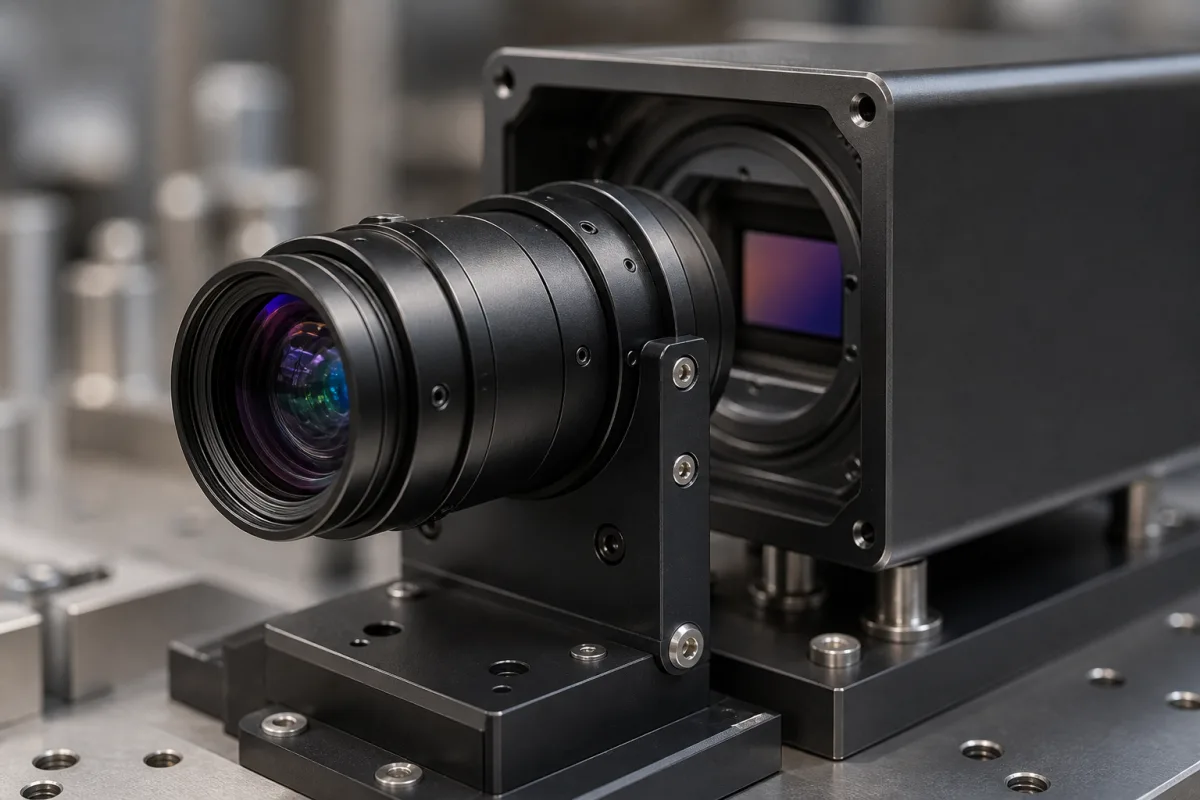
Representative product image. Confirm appearance and specifications with the manufacturer.

Product Specifications

Technical details and manufacturing context for Imaging Lens Assembly

Definition
The Imaging Lens Assembly is a precision optical component used within a 3D Optical Sensor Head. Its primary function is to collect incoming light from the target scene, correct optical aberrations, and focus the light accurately onto the image sensor. This assembly is critical for determining the resolution, field of view, and depth accuracy of the 3D measurement system. The assembly consists of multiple lens elements arranged to manipulate light rays, converging them onto the sensor plane to form a sharp image. Different lens elements correct for chromatic aberration, spherical aberration, and distortion to ensure high-fidelity image capture for subsequent 3D processing algorithms. The assembly is typically constructed with optical glass lenses and an aluminum alloy housing, providing mechanical stability and thermal performance. Key parameters include focal length (4–12 mm), aperture (F-number 1.4–2.8), optical distortion (<1.5%), modulation transfer function (>0.3 @ 50 lp/mm), back focal length (5–15 mm), operating temperature (-20 to 70 °C), storage temperature (-40 to 85 °C), relative humidity (20–80% RH, non-condensing), ingress protection rating (IP50–IP65 per IEC 60529), lens material (glass), weight (10–50 g), and dimensions (Ø20–30 mm × 15–25 mm). These values are reference ranges and must be verified for the specific model and application. The assembly is designed to integrate with the sensor package and camera housing, and its performance directly impacts the accuracy of 3D measurements. Proper selection requires consideration of the sensor size, working distance, and environmental conditions. Verification of model-specific values and standards should be conducted with the legal manufacturer or supplier.
Working Principle
The assembly uses multiple lens elements to collect and focus light from the object onto the sensor plane. The lenses are arranged to converge light rays, forming a sharp image. Aberrations such as chromatic and spherical aberration are corrected by the lens design, and distortion is minimized to ensure accurate 3D mapping. The aperture controls light throughput and depth of field, while the focal length determines field of view and magnification. The back focal length must match the sensor package height. The assembly operates within specified temperature and humidity ranges to maintain focus and image quality.
Common Materials
Optical Glass, Aluminum Alloy
Technical Parameters
ParameterTypical rangeNotes & selection driver
Focal Length4–12 mmDetermines field of view and magnification.
Aperture (F-number)1.4–2.8Affects light throughput and depth of field.
Optical Distortion<1.5 %Lower distortion for accurate 3D mapping.
Modulation Transfer Function (MTF)>0.3 @ 50 lp/mmIndicates resolution and contrast.
Back Focal Length5–15 mmMust match sensor package height.
Operating Temperature-20–70 °COutside range may cause focus shift.
Storage Temperature-40–85 °CSurvival range for shipping and storage.
Relative Humidity20–80 %RHNon-condensing; condensation may cause fogging.
Ingress Protection (IP) RatingIP50–IP65Higher rating for dusty/humid environments.IEC 60529
Lens MaterialGlassGlass for thermal stability; plastic for cost.
Weight10–50 gAffects mounting and moving parts.
Dimensions (Diameter × Length)Ø20–30 × 15–25 mmMust fit within camera housing.

Ranges are indicative industry figures for RFQ preparation, not a supplier commitment. Confirm every value and standard with the legal manufacturer before ordering.

Components / BOM
  • Lens Elements Part
    Refract and focus light rays; individual elements correct for specific optical aberrations.
    Material: Optical Glass (e.g., BK7, SF11)
  • Lens Barrel
    Holds all lens elements in precise alignment and provides mechanical mounting to the sensor head.
    Material: Aluminum Alloy or Engineering Plastic
  • Mounting Flange Part
    Provides the standardized interface (e.g., C-mount, S-mount) for attaching the assembly to the 3D sensor housing.
    Material: Stainless Steel
  • Aperture
    Sets how much light gets through and how deep the focus stays.

Applied To / Applications

This component is essential for the following industrial systems and equipment:

Industrial Ecosystem & Supply Chain Structure

Complementary Systems
Downstream Applications
Specialized Tooling

Application Fit & Sizing Matrix

Operational Limits
pressure: 0 to 1 atm (sealed assembly)
other spec: Max humidity: 85% RH non-condensing
temperature: -20°C to +80°C
Media Compatibility
✓ Clean air environments ✓ Inert gas atmospheres (N2, Ar) ✓ Vacuum systems
Unsuitable: Abrasive particulate-laden environments
Sizing Data Required
  • Sensor format/size (e.g., 1/2", 2/3")
  • Working distance (object to lens distance)
  • Required field of view/angular coverage

Reliability & Engineering Risk Analysis

Failure Mode & Root Cause
Optical surface contamination/degradation
Cause: Accumulation of dust, oils, or particulates on lens surfaces from environmental exposure or handling, leading to reduced light transmission, image distortion, or permanent coating damage.
Mechanical misalignment or loosening
Cause: Vibration, thermal cycling, or improper assembly causing lens elements, mounts, or retaining rings to shift, resulting in focus drift, image blurring, or mechanical instability.
Maintenance Indicators
  • Visible haze, spots, or streaks on lens surfaces under inspection lighting
  • Audible rattling or shifting sounds when the assembly is gently moved, indicating loose internal components
Engineering Tips
  • Implement strict cleanroom handling protocols and periodic inert gas purging to minimize airborne contaminants and oxidation on optical surfaces
  • Use thread-locking compounds on mounting hardware and perform regular torque checks to maintain alignment under thermal and vibrational loads

Indicative industry ranges for design and RFQ preparation. Confirm the exact figures and applicable standard with the manufacturer before specifying.

Compliance & Manufacturing Standards

Applicable Standards
ISO 10110: Optical and photonic components ANSI Z80.1: Ophthalmic lenses DIN 3140: Tolerances for optical components

Quoted from the published standard.

Manufacturing Precision
  • Centering tolerance: +/- 0.01mm
  • Surface irregularity: λ/4 at 632.8nm
Quality Inspection
  • Interferometric surface testing
  • Modulation Transfer Function (MTF) measurement

Manufacturers of Imaging Lens Assembly

Manufacturer profiles associated with Imaging Lens Assembly.

Sourcing Imaging Lens Assembly from China?
Tell us your specification and target quantity — we will match it against manufacturer records and come back with the factories that fit.
Request manufacturers We manufacture this

Manufacturer listings support early research and capability understanding. They are not certification, ranking, or transaction guarantees.

Technical documentation
Request current drawings, revision history, and a signed specification sheet.
Manufacturing capability
Verify equipment lists, process limits, capacity, and representative production evidence.
Inspection readiness
Confirm test methods, calibrated equipment, sampling plans, and traceable reports.
Supplier transparency
Check the legal entity, factory address, ownership, certifications, and direct contacts.

CNFX does not score or rank suppliers. Buyers must verify all claims and documents with the legal manufacturer before ordering.

Supply Chain Compatible Machinery & Devices

Industrial Smart Camera Module

The Industrial Smart Camera Module is a compact, self-contained vision processing unit designed for integration into industrial machinery and production lines.

Explore Specs →
Surface Mount Resistor

Passive electronic component for current limiting and voltage division in circuits

Explore Specs →
Surface Mount Capacitor

A surface mount capacitor is a fundamental electronic component used for energy storage, filtering, coupling, and decoupling in electronic circuits.

Explore Specs →
Surface Mount Technology (SMT) Pick-and-Place Machine

Automated machine that precisely places electronic components onto printed circuit boards.

Explore Specs →

Frequently Asked Questions

What is the primary function of the imaging lens assembly?

It collects light from the target scene, corrects optical aberrations, and focuses it accurately onto the image sensor, which is essential for determining resolution, field of view, and depth accuracy in 3D measurement systems.

What materials are typically used in this assembly?

The assembly commonly uses optical glass for the lens elements and aluminum alloy for the housing, providing optical clarity and mechanical stability.

How does the focal length affect the 3D system?

Focal length determines the field of view and magnification. A shorter focal length provides a wider field of view, while a longer one offers higher magnification, affecting the measurement range and resolution.

Why is the ingress protection rating important?

The IP rating indicates the level of protection against dust and moisture. A higher rating (e.g., IP65) is suitable for dusty or humid environments, ensuring reliable operation and preventing fogging or damage.

Data Basis

Editorial classification, named public sources where available, and source-reviewed manufacturer records.

Preliminary Technical Classification
This page supports structured research, RFQ preparation, and supplier evaluation. It does not replace buyer-led supplier qualification, standards review, or technical approval.
Buyer enquiry

Request manufacturing insight for Imaging Lens Assembly

Ask for use case, specification boundaries, supplier type, and RFQ preparation information for this product.

Where it goes
Straight to the CNFX editorial desk, and to the manufacturer if this product is linked to a claimed profile. Nothing is broadcast to a supplier list.
Your details stay here
We do not sell or rent enquiry data, and we do not add you to a mailing list. Used only to answer this request.
No commission, no middleman
CNFX is a directory. We take no cut of any order and never negotiate on a supplier's behalf.
What we don't claim
A listing is not an endorsement. Qualify every supplier and verify every figure yourself before ordering.

Your business information is used only to process this request.

Thank you! Your message has been sent. We'll respond within 1–3 business days.
Sorry, we couldn't send your message. Please try again, or email us at contact@cnfx.com.

Need to Manufacture Imaging Lens Assembly?

Compare manufacturer profiles with relevant product and process capability.

Previous Product
XY Positioning Stage
Last Product
Get QuotesChat