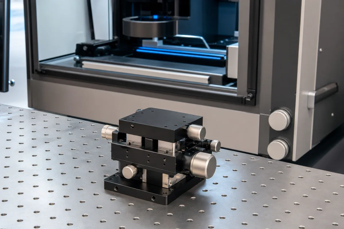
Micro-adjustment mechanism for optical alignment: fine-pitch, differential and piezo screws that set an optic to the micrometre
The screw that moves an optic by micrometres · 0.5 mm lead with 0.01 mm graduations, 0.1 mm fine-pitch heads, 0.05 and 0.025 mm differential leads reading to 0.5–1 µm over a 0.2–0.25 mm fine range, and a self-locking piezo replacement stepping 20 nm
Aligning a lens, fibre or mirror ends with a turn of a knob: a screw pushes a stage or mount against a spring, and the thread lead, the scale on the thimble and the load the screw can push decide how finely and how far it can move. This page compares the three ways makers get below the 10 µm reading of an ordinary micrometer head (a finer thread, two threads working against each other, or a worm gear) and the piezo inertia actuator that replaces the knob when the adjustment must be made remotely or held without drift.
Manual and piezo-driven micro-adjusters that position optical stages and mounts: fine-pitch micrometer heads, differential screws and differential micrometer heads, worm-drive micrometer heads, and piezo inertia actuators made to replace them. Threaded retaining, lock and spacer rings that hold lenses in barrels are covered on the Precision optical lens mounting ring page, and athermal barrel assemblies on the Athermal lens barrel assembly page. The stacked XY, Z, rotation and tip-tilt stages these adjusters drive are covered on the Manual multi-axis alignment stage page, and motorised stages on the Precision positioning stages page; flexure nanopositioners and complete lens-centring machines are outside this page.
CNFX editorial research · Sources checked October 13, 2026 · 3 sources
From 0.5 mm to 0.025 mm per turn: how the thread lead sets what one thimble division moves
Every head below divides a turn of the thimble into a scale; what changes is how far one turn moves the spindle.
Mitutoyo states that the 148 series' 0.1 mm pitch is for extra-fine adjustment and positioning, lists semiconductor wafer positioning machinery, optical component alignment units and precision X-Y tables as applications, and keeps the outside dimensions compatible with conventional 0.5 mm pitch heads so it can replace them. [2] For the 110 series it attributes the fine feed to the differential movement of spindle threads and nuts, with a non-rotating spindle and carbide-tipped face. [2]
Editorial calculation: a 0.5 mm lead read to 0.01 mm and a 0.025 mm lead read to 0.0005 mm both put 50 divisions on one turn; the differential head reads 20 times finer because it moves 20 times less per turn, not because its scale is finer.
Editorial note: a reading is not an accuracy. Mitutoyo gives ±2 µm for the 148 series against a 2 µm graduation, and lists accuracy as ±3 / ±1.5 µm for 110-series heads that read to 0.1 µm. [2]
State the smallest step the optic needs, the total travel, and whether the scale must be read to that step or only the motion must be that fine.
02
A 0.2–0.25 mm fine range and as little as 9.8 N: what a differential head trades for its resolution
Differential heads combine a full-length coarse drive with a short fine drive, and the published load ratings fall as the fine lead shrinks. [1][2]
Editorial calculation: the MHF2-13's 0.2 mm fine travel is 1.5% of its 13 mm coarse travel and corresponds to 8 turns of the 0.025 mm fine lead; the coarse drive must first bring the optic within 0.2 mm of where it should be. Its 9.8 N rating is one-third of the 29.4 N of the 0.05 mm-lead screws, so the return spring and stage friction have to be checked against it.
OptoSigma's WGP-13 worm-drive head takes a different route: its fine or coarse knob can be used at any position along the 13 mm travel, with 0.5 µm resolution over the entire travel and a non-rotating spindle. [1] Editorial note: for an adjustment that has to be fine at more than one point across the travel, that avoids re-setting the coarse drive each time; ask for its load rating, which the page reviewed does not give.
Give the preload spring force and stage friction the adjuster must push, the travel over which fine motion is needed, and whether the tip must not rotate against the mount.
03
A piezo inertia drive in place of the thimble: 20 nm steps, 100 N held without current, 7 mm at 2 mm/min
Physik Instrumente offers its N-472 PiezoMike for alignment of mechanical and optomechanical components. It mounts by an M10×1 thread or a clamping shank, drives a stainless-steel screw with a stick-slip inertia drive, and measures motion with an integrated incremental encoder. [3]
PI states that the drive is self-locking at rest, needs no current and generates no heat, holding the position with maximum force even when closed-loop control is switched off. Its data are specified at 22 ± 3 °C and for unloaded conditions unless stated, and PI defines its typ. values as a statistical average, not a value guaranteed for every unit. [3]
Editorial calculation: at 2 mm/min the full 7 mm takes 3.5 minutes, so the actuator suits set-and-hold alignment, not repeated motion; its 22 N feed force sits between the 9.8 N and 29.4 N ratings of the manual differential heads above, and its 100 N holding force exceeds both.
More than 1,000,000,000 steps at ambient conditions; more than 50,000,000 in vacuum [3]
Materials
Stainless-steel screw; aluminium and bronze housing; 200 g (250 g vacuum version) [3]
Say whether the adjustment must be made remotely, in vacuum or with the controller switched off afterwards, and give the preload the actuator works against.
04
What to send for a micro-adjustment mechanism
Paste it into your enquiry below or into an email to a maker, then replace every bracket.
Optic: [lens / mirror / fibre; mass; mount type]
Motion: [smallest step; total travel; fine range needed]
Load: [spring preload; friction]
Reading: [scale graduation; encoder]
Interface: [mounting thread or shank; tip shape; non-rotating spindle]
Drive: [manual / piezo; remote or vacuum use]
Hold: [drift allowed; power-off holding]
Explore company information and manufacturing capabilities, then discuss the scope of your project with a relevant supplier.
Share this page
Compiled and source-reviewed by the CNFX editorial team.
Each manufacturer above links to the page on that company's own website where the product is listed, with the date we checked it. How we source and review
· Page last updated 13 October 2026
Buyer questions
How does a differential micrometer get finer resolution?
Mitutoyo attributes it to the differential movement of spindle threads and nuts, giving 0.05 mm (or 0.025 mm) of spindle feed per turn instead of 0.5 mm; OptoSigma's MHF2-13 reads 0.5 µm on its 0.025 mm fine drive. [2][1]
How far does the fine drive of a differential head move?
OptoSigma's differential screws have 0–0.25 mm fine travel and its MHF2-13 0–0.2 mm; Mitutoyo's 110-502 has a 0.2 mm narrow range within one revolution. [1][2]
Is a 0.1 mm pitch micrometer head interchangeable with a 0.5 mm one?
Mitutoyo states that its 148 series with 0.1 mm pitch keeps external dimensions compatible with conventional 0.5 mm pitch heads; graduation is 0.002 mm and accuracy ±2 µm. [2]
Can a piezo actuator replace a micrometer screw?
PI's N-472 PiezoMike mounts by M10×1 thread or shank, steps 20 nm open loop, travels 7 mm at up to 2 mm/min and holds 100 N without current. [3]
Sources and what still needs a direct check
Sources checked 2026-10-13. Differential screw, differential micrometer and worm-drive data come from OptoSigma's manual actuator product pages; fine-pitch and differential micrometer head data from Mitutoyo's micrometer head catalogue; piezo inertia actuator data from PI's N-472 PiezoMike product page.