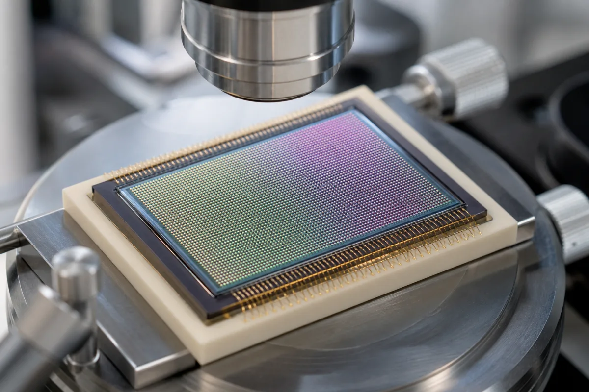
Micro-lens array on an image sensor: on-chip reflowed microlenses over each pixel
On-chip microlenses over image-sensor pixels · resist thickness and reflow window, gap between lenses and bridging, split-dose exposure, thinner lenses at the array edge
Each pixel of a camera image sensor sits under its own tiny lens that gathers light falling on the pixel area and steers it past the metal wiring onto the photodiode. These lenses are not separate parts: they are formed on the finished sensor wafer, above the colour filters, by patterning a transparent photoresist into blocks and heating it until surface tension rounds each block into a lens. The quality of the array rests on three things: how far apart the lenses end up, how high they are, and whether neighbours bridge during reflow.
On-chip microlens arrays formed on image-sensor wafers (CMOS and CCD) above the colour filter array, by photoresist patterning and thermal reflow, with their dimensions, gaps and height profiles across the array. Moulded multi-lens arrays placed over LED boards in luminaires are covered on the Precision optical lens array page. Free-standing glass or fused-silica microlens arrays and beam homogenisers, and camera objective lenses, are outside this page.
CNFX editorial research · Sources checked October 12, 2026 · 3 sources
Resist thickness, reflow temperature and the lens diameter and height that result
Patents from foundries and sensor makers state the windows they use; the lens shape follows from the resist volume and the reflow.
TSMC's US 7,704,778 B2 describes the sequence: a layer of microlens material, a photoresist, is exposed and developed into a pattern over the photo-sensitive elements, then reflowed so that each block takes a substantially hemispherical shape; its preferred reflow is a thermal process at about 100 °C to 200 °C for about 10 seconds to about 30 minutes. The patent explains why this gets harder as pixels shrink: microlenses placed closer together “have a tendency to merge during the reflow procedure,” and thicker device stacks with more metal layers lengthen the focal distance and call for thinner lenses, whose reflow uses a higher temperature and so raises the risk of merging. [1]
VisEra's US 8,283,110 B2 coats a photosensitive layer, for example a positive photoresist or photosensitive polyimide, about 0.5 µm to 3.0 µm thick over a transparent layer on the colour filters, and reflows the patterned structures at about 150 °C to about 250 °C. The resulting microlenses have a diameter greater than 1.5 µm, preferably about 2 µm to 6 µm, and a height greater than 0.5 µm, preferably about 0.7 µm to 2.0 µm. [2]
Editorial calculation: a hemispherical cap 2 µm across would be 1 µm high; VisEra's preferred 0.7–2.0 µm heights over 2–6 µm diameters therefore range from shallower than a hemisphere on the wider lenses to close to one on the narrow lenses.
For a sensor design or a foundry process, state the pixel pitch, the stack height from photodiode to lens, the colour filter and planarisation layers, the lens material and its transmittance, the target lens height and gap, and the reflow temperature the underlying layers can take.
02
Narrowing the gap between neighbouring microlenses without bridging
Both patents below treat the gap left between lenses after reflow as the figure to shrink, and bridging as the limit.
Dongbu HiTek's US 7,723,147 B2 states that in microlens forming the gap between neighbouring lenses may have the largest effect on sensor performance, and that a smaller gap can improve light sensitivity by as much as 10 to 15% or more. When the gap is set by the photolithographic pattern before reflow, lithographic resolution limits its minimum width to about 50 nm, and reflowing further risks a lens bridge that joins neighbours; the patent aims at gaps below 50 nm with a lower bridging risk. [3]
TSMC's approach exposes the microlens layer more than once through the same mask at different focal planes, each exposure using about 0.7 to 1.0 of the dose that would clear the full thickness divided by the number of exposures: with a layer that needs 240 mJ, two exposures of about 84 mJ to 120 mJ, or three of about 56 mJ to 80 mJ. The lower doses let a smaller critical dimension be patterned between lenses, and the patent prefers a gap after reflow below about 0.2 µm, more preferably below about 0.1 µm, to improve quantum efficiency. An optional bleaching step before reflow reduces photoactive material, limiting degradation at reflow temperature and improving transmissivity. [1]
Editorial calculation: TSMC's preferred 0.1 µm gap is twice the 50 nm lithographic limit Dongbu cites, which shows why both patents look for ways to close the gap during or after reflow rather than at the mask.
03
Lower lenses at the edge of the array to flatten the focal plane
One array does not have to carry identical lenses; VisEra makes two heights on the same sensor.
VisEra trims part of each resist block in the edge region of the sensor using a second photomask with segments of different transmittance, while the centre region is protected, so that after reflow the edge microlenses are lower than those in the centre; the patent states that this gives a planar focal plane and reduces field curvature caused by differences in focal length between the microlenses. [2]
Paste it into your enquiry below or into an email to a maker, then replace every bracket.
Sensor: [pixel pitch; array size; chief ray angle at the edge]
Stack: [photodiode to lens height; colour filter; planarisation]
Lens: [material; diameter; height; centre and edge profile]
Gap: [target after reflow; bridging limit]
Process: [resist thickness; exposure scheme; reflow temperature and time; bleaching]
Checks: [height and gap measurement; transmittance; reliability]
Explore company information and manufacturing capabilities, then discuss the scope of your project with a relevant supplier.
Share this page
Compiled and source-reviewed by the CNFX editorial team.
Each manufacturer above links to the page on that company's own website where the product is listed, with the date we checked it. How we source and review
· Page last updated 13 October 2026
Buyer questions
How are microlenses made on an image sensor?
A transparent photoresist is patterned into blocks over the pixels and heated so that each block reflows into a lens; TSMC's patent gives about 100–200 °C for 10 seconds to 30 minutes. [1]
How big is an on-chip microlens?
VisEra's patent gives diameters preferably of about 2–6 µm and heights of about 0.7–2.0 µm, from a resist layer about 0.5–3.0 µm thick. [2]
Why does the gap between microlenses matter?
Light falling in the gap misses the lens; Dongbu HiTek states that a smaller gap can raise light sensitivity by as much as 10–15%, but lithography alone limits the gap to about 50 nm before bridging becomes a risk. [3]
Sources and what still needs a direct check
Sources checked 2026-10-12. Three patents, from TSMC, VisEra and Dongbu HiTek, describe how on-chip microlenses are formed; values are those stated in their embodiments, not a foundry's process specification.