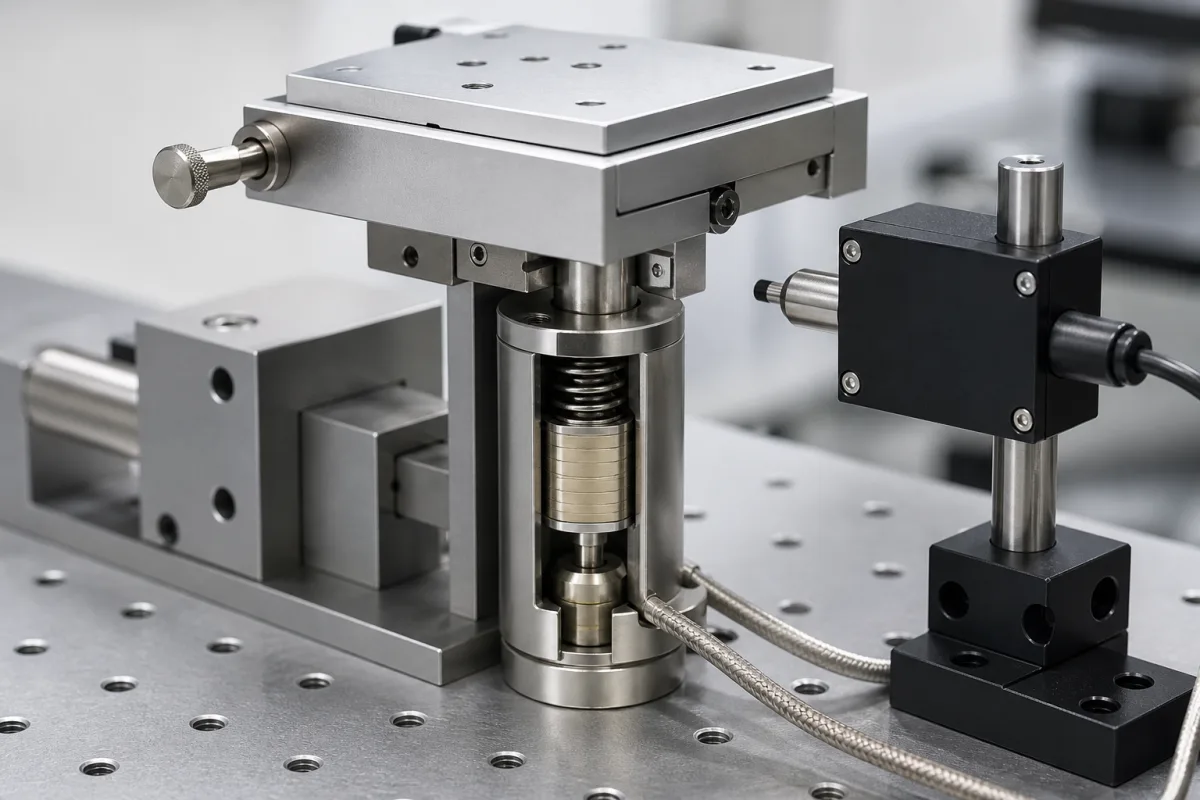
The illustrated actuator, a ceramic stack under a preload spring in a steel housing, lifts a small stage while a sensor on its own post watches the platform. That pairing is the subject here. A piezo stack's travel per volt is not constant, the curve opens into a hysteresis loop, and after a voltage step the stack keeps moving for minutes. Whether that matters depends on how the actuator is driven: open loop on voltage, open loop on charge, or closed loop on a position sensor.
Covers the positioning behaviour of piezo stack actuators and how it is controlled: nonlinearity, hysteresis and creep in open-loop voltage operation, drift after the voltage is removed, closed-loop control with capacitive, strain-gauge, piezoresistive or encoder sensors, and charge control for dynamic use. Stack construction, travel, blocking force, stiffness, capacitance, preload and drive voltage are on Piezoelectric Stack Actuator (5807); positioning stages and their accuracy tests on XYZ Positioning Stage (3622) and Multi-Axis Positioning System (2926).
CNFX editorial research · Sources checked October 13, 2026 · 3 sources
Open loop on voltage: a nonlinear, hysteretic curve that keeps creeping 1–2% per time decade
PI Ceramic describes the voltage-to-displacement curve of a piezo actuator as strongly nonlinear and subject to hysteresis, so intermediate positions cannot be interpolated linearly from the nominal displacement. Datasheets give free displacement at nominal voltage only.
Applied to a 10 µm step, PI Ceramic's creep law gives 10.2–10.4 µm after 10 s and 10.46–10.91 µm after one hour, for γ = 0.01 and 0.02 (Editorial calculation). For a hold of an hour, open-loop voltage drive is therefore off by up to about 0.9 µm on a 10 µm move, measured from the 0.1 s position (Editorial calculation).
Free displacement on the datasheet also depends on preload, temperature, drive frequency, dimensions and passive material, so the figure at nominal voltage is a starting point, not a position calibration.
Effect
What PI Ceramic and Linear Motion Tips state
Nonlinearity
Displacement per volt changes along the curve; in PI Ceramic's Fig. 3 data the large-signal deformation coefficient d(GS) increases with field amplitude
Hysteresis
Strong in open-loop voltage operation, defined as maximum opening of the curve over maximum displacement; especially high for shear actuators and with bipolar drive; semibipolar drive gains stroke at the cost of more nonlinearity and hysteresis
Creep
Displacement keeps changing after a voltage step at constant voltage; creep speed decreases logarithmically; ΔL(t) = ΔL(0.1 s)·(1 + γ·log(t / 0.1 s)) with γ about 0.01 to 0.02, i.e. 1–2% per time decade
Creep over time (LMT)
Creep between 10 s and 100 s is similar to creep between 0 s and 10 s, and it always runs in the direction of the voltage change
Drift (LMT)
Used by some makers for continued motion after the voltage is removed, as the dipoles relax; also for thermal drift
The creep figures assume PI Ceramic's γ range; use the factor for the specific actuator where the maker states one.
02
Which sensor closes the loop: capacitive, strain gauge, piezoresistive or encoder
Physik Instrumente compares the four sensor types it uses in nanopositioning systems. Its ratings refer to complete systems, including controller and mechanics, checked with an external Zygo interferometer.
The split between direct and indirect matters for what the loop corrects. A strain gauge is a metal or semiconductor foil bonded to the piezo ceramic or, for better precision, to the flexure guide; the platform position is inferred from that strain, so errors between the gauge and the platform stay outside the loop. PI uses full-bridge circuits with more than one gauge per axis to improve thermal stability. A capacitive sensor measures the platform itself without contact, which is the arrangement the illustration suggests with its sensor on a separate post.
PI Ceramic offers strain gauges applied to its PICA Stack and PICA Power actuators for position-controlled builds; PI's position-controlled systems, with capacitive or strain-gauge sensors combined with suitable guiding mechanics, a low-noise amplifier and control algorithms, reach positioning accuracies in the subnanometre range.
Sensor
Resolution
Linearity
Stability / repeatability
Bandwidth
Measurement
Range
Capacitive
excellent
excellent
excellent
excellent
direct, noncontact
< 2 mm
Strain gauge (SGS)
very good
very good
good
very good
indirect, with contact
< 2 mm
Piezoresistive (PRS)
excellent
good
average
very good
indirect, with contact
< 1 mm
Linear encoder
excellent
very good
excellent
very good
direct, noncontact
up to > 100 mm
PI warns that system data on resolution, linearity and repeatability must not be confused with the theoretical data of the sensor alone.
03
Voltage, charge or closed loop: matching the drive to the motion
PI Ceramic names two ways around the open-loop errors, with different reach.
The charge-control and closed-loop rows are PI Ceramic's statements. For a stage that holds a position for minutes or hours, the creep calculation above is the case for closing the loop.
Drive mode
Effect on hysteresis and creep
Where it fits
Voltage, open loop
Full hysteresis and creep as above
Not addressed in the cited sources
Charge-control amplifier
Hysteresis reduced to 1–2% without a position sensor
Applications with purely dynamic control
Closed loop on a position sensor
The route PI Ceramic ranks first for eliminating hysteresis and creep
Static holds and precise positioning
Stage design, preload and drive electronics also set the noise floor and bandwidth that a closed loop can reach.
04
What to ask for a closed-loop piezo actuator
Paste it into your enquiry below or into an email to a maker, then replace every bracket.
State the travel, the load and preload, the positions to hold and for how long, the step and settling requirements, the frequency content of dynamic moves, temperature, and whether an outer loop exists. Ask for open-loop hysteresis and creep data, the sensor type and whether it measures the platform directly, closed-loop resolution, linearity and repeatability as system values and how they were verified, bandwidth, and the amplifier type (voltage, charge or closed loop).
Explore company information and manufacturing capabilities, then discuss the scope of your project with a relevant supplier.
Share this page
Compiled and source-reviewed by the CNFX editorial team.
Each manufacturer above links to the page on that company's own website where the product is listed, with the date we checked it. How we source and review
· Page last updated 13 October 2026
Buyer questions
How much does a piezo actuator creep?
PI Ceramic gives a creep factor γ of about 0.01 to 0.02, 1–2% of the displacement change per time decade after a voltage step; on a 10 µm step that is 10.46–10.91 µm after an hour (Editorial calculation). [1]
Does creep stop?
It slows logarithmically. Linear Motion Tips notes that creep between 10 and 100 s is similar to creep between 0 and 10 s, and that it runs in the same direction as the voltage change. [3]
Capacitive or strain-gauge feedback?
In PI's comparison, capacitive sensors measure the platform directly and rate excellent on resolution, linearity and stability; strain gauges measure indirectly on the stack or guide and rate good on stability, with full bridges improving thermal stability. [2]
Can hysteresis be reduced without a sensor?
Yes, for purely dynamic control: PI Ceramic states that a charge-control amplifier reduces hysteresis to 1–2% without closed-loop control. [1]
Sources and what still needs a direct check
Sources checked 2026-10-13. Two Physik Instrumente pages, one on actuator displacement behaviour from PI Ceramic and one comparing position sensors, and a Linear Motion Tips article on creep and drift.